
Optical phase-locked loop device and phase-locked method based on direct digital frequency synthesizer

A frequency synthesizer, digital technology, applied in electromagnetic receivers, electromagnetic transmitters, electrical components, etc., can solve problems such as phase-locked control bandwidth limitation, improve control bandwidth, ensure reliability, and achieve the effect of automatic tracking

Active Publication Date: 2020-05-05
SHANGHAI INST OF OPTICS & FINE MECHANICS CHINESE ACAD OF SCI
View PDF6 Cites 0 Cited by
  • Summary
  • Abstract
  • Description
  • Claims
  • Application Information

AI Technical Summary

Problems solved by technology

Since the conversion of frequency and phase brings about a 90-degree phase shift in the control loop, the phase delay left for other parts of the control loop is only 45 degrees, and the phase-locked control bandwidth is severely limited

Method used


Image

  • Optical phase-locked loop device and phase-locked method based on direct digital frequency synthesizer
  • Optical phase-locked loop device and phase-locked method based on direct digital frequency synthesizer
  • Optical phase-locked loop device and phase-locked method based on direct digital frequency synthesizer

Examples


Embodiment Construction

[0025] The present invention will be further described below in conjunction with the embodiments and accompanying drawings, but the protection scope of the present invention should not be limited thereby.

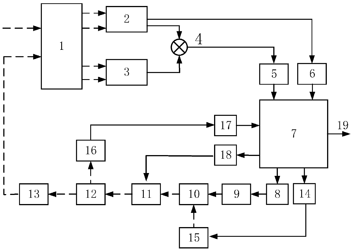
[0026] figure 1It is a structural block diagram of the optical phase-locked loop device based on the direct digital frequency synthesizer of the present invention. The solid line part is the connection of the electrical signal, and the dotted line is the connection of the optical signal. As can be seen from the figure, the present invention is based on an optical phase-locked loop device of a direct digital frequency synthesizer, comprising a 90-degree optical bridge 1, a first balanced detector 2, a second balanced detector 3, a mixer 4, a first mode Digital converter 5, serial-parallel conversion chip 6, FPGA7, DDS8, band-pass microwave amplifier 9, optical intensity modulator 10, fiber grating filter 11, fiber beam splitter 12, fiber amplifier 13, first digital-to-analo...


PUM


Abstract

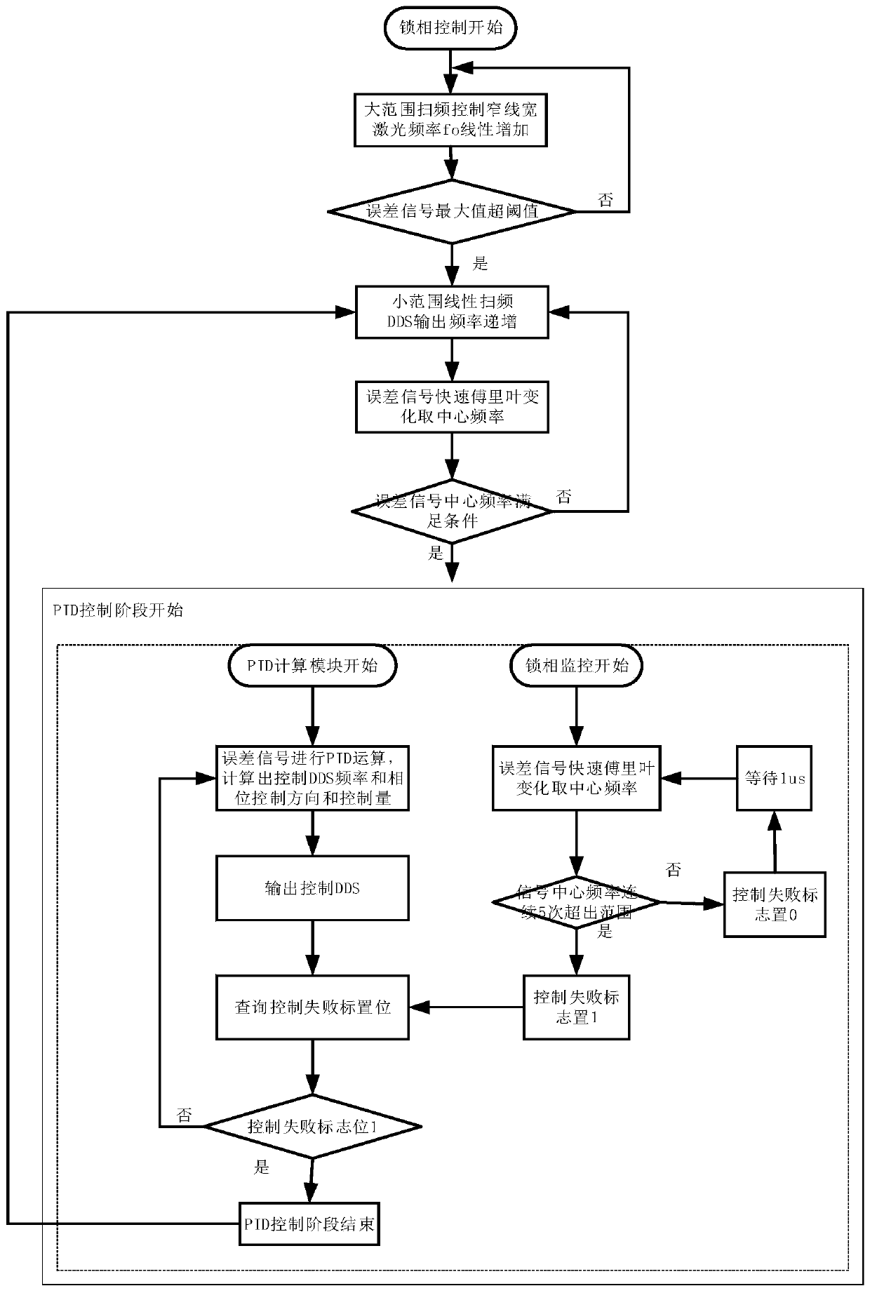
The invention relates to an optical phase-locked loop device based on a direct digital frequency synthesizer and a phase-locking method. The device is composed of a 90-degree optical bridge unit, a balanced detector, a mixer, a programmable logic gate array, a digital-to-analog converter, an analog-to-digital converter, a direct digital synthesizer, a band-pass microwave amplifier, a narrow-line-width tunable laser device, an optical intensity modulator, a fiber grating filter, a fiber beam splitter, and a fiber amplifier. The software uses linear frequency sweeping and Fourier transform to realize the initial entry of the phase-locked loop. With a PID algorithm, precise phase control of the optical phase-locked loop is realized. The device is able to realize high-precision phase locking and large-range frequency shift compensation of the optical phase-locked loop without an auxiliary phase-locked capture circuit. The DDS is used for replacing a voltage-controlled oscillator to realizedirect conversion from the voltage to the phase; and the loop phase margin is improved, the control bandwidth is enhanced, and thus the phase-locked performance of the optical phase-locked loop is improved. Therefore, the optical phase locking and laser coherent communication signal demodulation are realized quickly.

Description

technical field [0001] The invention relates to free space coherent communication and optical fiber coherent communication, in particular to an optical phase-locked loop device and a phase-locked method based on a direct digital frequency synthesizer. Background technique [0002] Laser coherent communication has the advantages of high sensitivity, large communication bandwidth and dense wavelength division multiplexing. It is a technical hotspot in optical fiber communication and is gradually replacing laser intensity modulation communication on the backbone network. Laser coherent communication requires phase synchronization or phase locking between the local laser at the receiving end and the signal laser at the transmitting end. Due to the difficulty of optical phase-locked loop technology, DSP (Digital Signal Processing) is mainly used in China to process the signal algorithm and then perform phase estimation and signal demodulation. This method does not require precis...

Claims


Application Information

Patent Timeline
Patent Type & Authority Patents(China)
IPC IPC(8): H04B10/50H04B10/516H04B10/556H04B10/61H04B10/11
CPCH04B10/11H04B10/504H04B10/5165H04B10/556H04B10/6165
Inventor 陈卫标岳朝磊孙建锋朱韧张晓曦刘磊
Owner SHANGHAI INST OF OPTICS & FINE MECHANICS CHINESE ACAD OF SCI
Learn More