Waste heat recovery device for oil-electric hybrid vehicle

A technology of waste heat recovery device and oil-electric hybrid power, applied in safety devices, noise reduction devices, exhaust devices, etc., can solve the problems of energy waste, high charging costs, low fuel utilization rate, etc., to reduce charging costs and energy loss The effect of less and compact device structure

Pending Publication Date: 2018-04-20
BEIJING UNIV OF TECH
View PDF7 Cites 18 Cited by
  • Summary
  • Abstract
  • Description
  • Claims
  • Application Information

AI Technical Summary

Problems solved by technology

However, there are still some problems in gasoline-electric hybrid vehicles, such as: when the internal combustion engine works alone, the fuel utilization rate is low. From the perspective of the energy balance of the internal combustion engine for vehicles, it is only 30%-45% (diesel engine) or 20%-30% (Gasoline engine) The total heat of fuel combustion is used for power output, friction loss and mechanical loss are about 10% of the total heat of fuel combustion, and the rest of the energy is mainly discharged into the atmosphere through cooling medium and high-temperature exhaust gas, causing serious energy waste; When the power source is a high-power battery and the mileage is long, it is necessary to pre-charge the battery for a long time, resulting in high charging costs, etc.

Method used


Image

  • Waste heat recovery device for oil-electric hybrid vehicle
  • Waste heat recovery device for oil-electric hybrid vehicle

Examples


Embodiment 1

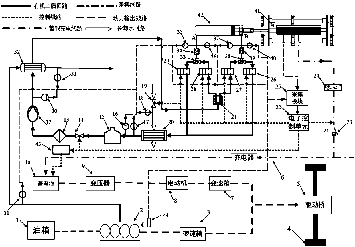
[0028] figure 1 It is a schematic diagram of the waste heat recovery system device of a gasoline-electric hybrid vehicle. The device mainly includes an internal combustion engine exhaust heat recovery system, an energy storage charging system, a power output system, and an acquisition control system. The above internal combustion engine exhaust waste heat recovery system includes internal combustion engine 2, exhaust passage, evaporator 32, flow divider 21, first three-way valve 33, second three-way valve 38, free piston expander 42, condenser 20, storage The liquid tank 15, the first electric valve 14, the working medium filter 13, the working medium pump 12 and the connected working medium pipeline; the above-mentioned energy storage charging system includes a free piston expander 42, a permanent magnet cylindrical linear generator 41 , rectifier 24, switch relay 23, charger 6, storage battery 10 and connecting circuit; The above-mentioned power output system includes drive ...


PUM


Abstract

The invention relates to a waste heat recovery device for an oil-electric hybrid vehicle and belongs to the technical field of waste heat recovery. High-temperature tail gas enters an evaporator through an exhaust pipeline after being exhausted out of an internal combustion engine, heat is transferred to a liquid organic working medium, and the liquid organic working medium is turned into a high-temperature high-pressure gaseous organic working medium. Through control of a collection control unit over an electromagnetic valve, the high-temperature high-pressure gaseous organic working medium flows into a free piston expander, expands to work, and pushes a piston to reciprocate. After working in the free piston expander, the high-temperature high-pressure gaseous organic working medium is turned into a low-temperature low-pressure organic working medium, the low-temperature low-pressure organic working medium is discharged out of the free piston expander, flows through a condenser and is condensed into the liquid organic working medium, and the liquid organic working medium flows back to a liquid storage tank. In the reciprocating process, the piston in the free piston expander drives a permanent magnet type cylindrical linear generator rotor to conduct magnetic induction line cutting movement to generate electric energy for charging a storage battery of the oil-electric hybridvehicle, and power output is achieved again. By means of the waste heat recovery device for the oil-electric hybrid vehicle, waste heat of the tail gas can be efficiently recovered for charging the storage battery, and thus environment pollution and charging cost are reduced.

Description

technical field [0001] The invention relates to a waste heat recovery device that can be used for a hybrid electric vehicle, and specifically relates to the field of energy saving and emission reduction of an internal combustion engine, which can efficiently recover waste heat from the exhaust of the internal combustion engine of the hybrid electric vehicle and convert it into electric energy for power output. Background technique [0002] The pollution caused by automobile exhaust to the atmospheric environment is becoming more and more serious, and it has become one of the most difficult and urgent problems in the atmospheric environmental pollution. The development and popularization of new energy vehicles is an inevitable trend to realize the security of my country's energy strategy and maintain the sustainable development of the automobile industry. Hybrid vehicles have received the favor of the majority of automobile manufacturers due to their superior performance and g...

Claims


Application Information

Patent Timeline
Patent Type & Authority Applications(China)
IPC IPC(8): F01N5/02F01B23/10F01B25/10F01B11/00
CPCF01B11/00F01B23/10F01B25/10F01N5/025F01B2250/001F01B2250/002Y02T10/12
Inventor 田亚明张红光杨富斌侯孝臣李健赵蕊李天琨
Owner BEIJING UNIV OF TECH
Why Eureka
Try Eureka