Supercharge Your Innovation With Domain-Expert AI Agents!

Device for direct conversion of atomic thermal energy into electrical energy

An atomic and thermal energy technology, applied in the field of thermal energy conversion, can solve problems such as limited application area and direction, limited heat conversion rate, and limited lifespan, and achieve the effects of subsequent pollution, energy saving, environmental protection, low maintenance costs, and reduced capital investment

Pending Publication Date: 2018-05-04
文志强
View PDF0 Cites 0 Cited by
  • Summary
  • Abstract
  • Description
  • Claims
  • Application Information

AI Technical Summary

Problems solved by technology

[0013] 2. For solar power generation, it occupies too much area, high investment, and limited heat conversion rate
Low heat transfer rate, limited application area and direction
low heat transfer rate
Large equivalent ratio
[0015] 4. For PN semiconductor heat exchange batteries, the heat exchange power rate is only 40%
[0016] 5. For the graphene titanium anode lithium battery, it converts chemical energy into electrical energy, and the oxidation loss of the material is fast, with disadvantages, limited life, and secondary pollution

Method used


Image

  • Device for direct conversion of atomic thermal energy into electrical energy
  • Device for direct conversion of atomic thermal energy into electrical energy
  • Device for direct conversion of atomic thermal energy into electrical energy

Examples


Embodiment Construction

[0034] Attached below figure 1 to attach Figure 5 The present invention will be further described.

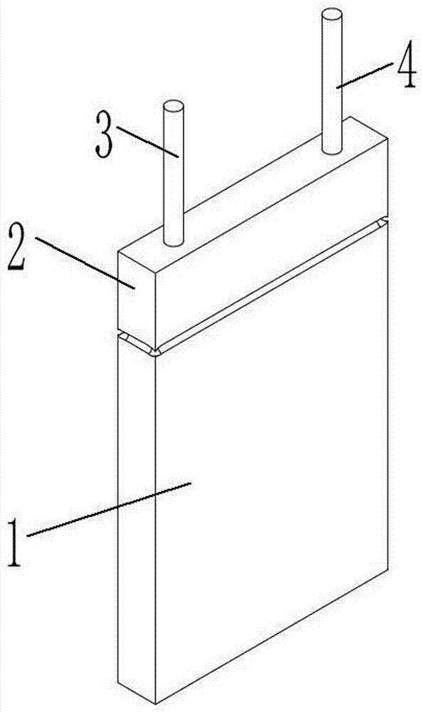
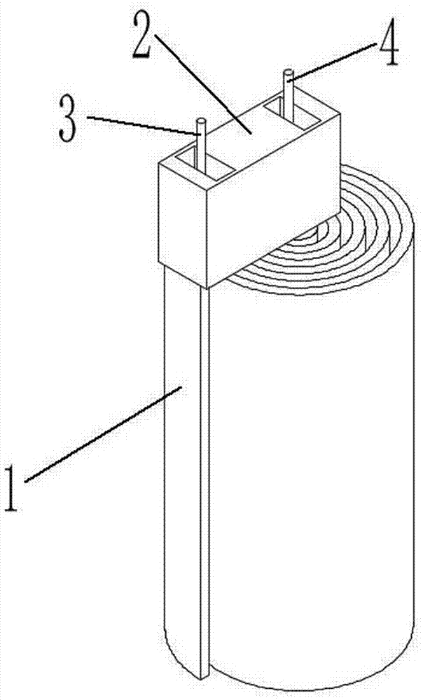
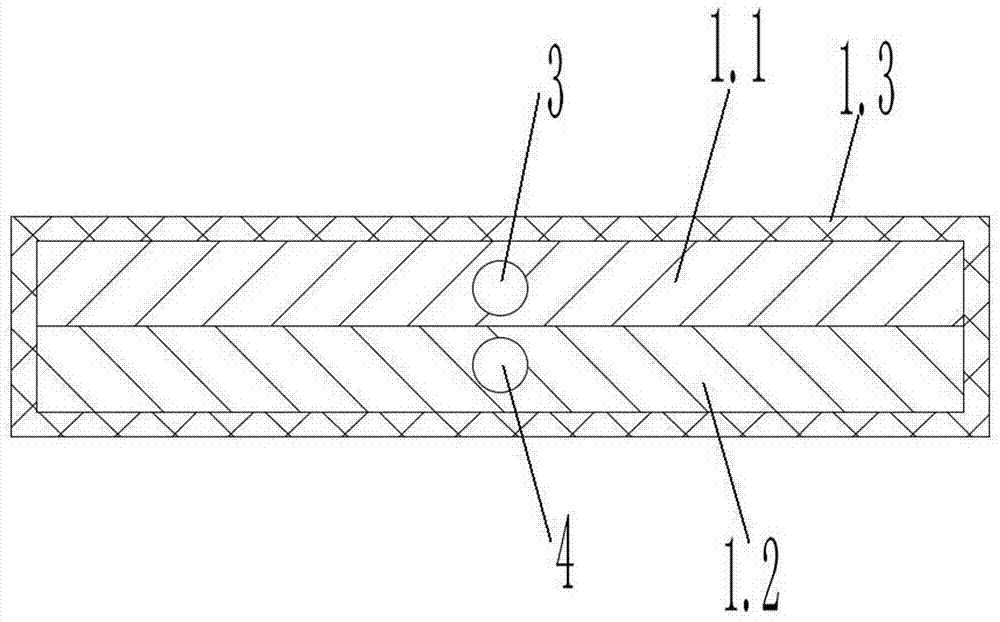
[0035] as attached figure 1 And attached image 3 As shown, a device for directly converting atomic thermal energy into electrical energy includes: an electrogenic base 1, which is composed of several layered negative electric energy atomic material layers 1.1 and several layered ionization energy atomic material layers 1.2. The electric energy atomic substance layer 1.1 is made of graphene material, the ionization energy atomic substance layer 1.2 is made of titanium alloy material, the negative electric energy atomic substance layer 1.1 and the ionization energy atomic substance layer 1.2 are sealed and wrapped with a ceramic insulating layer 1.3; electron accelerator 2. It is set on the upper end of the electricity generating base 1, and the electron-guiding fiber I 3 and the electron-guiding fiber II 4 are inserted vertically inside it. The lower end of the electron-gui...


PUM


Abstract

A device for the direct conversion of atomic thermal energy into electrical energy includes a power generation base, an electron accelerator, an electronic current guide fiber I and an electronic current guide fiber II. Lowest ionization energy material titanium alloy in the world and highest negative electricity energy material graphene are made into nanoscale flakes that are stacked alternatelyto form the power generation base. A power generation base block is placed in a high-temperature environment, so that peripheral electrons of an ionization energy material layer absorb heat and escapeto become free electrons, and are absorbed and gathered through a negative electricity energy atom material layer to form an electron group, and after the electron group is accelerated by the electron accelerator, the electron group supplies power to a load through the electronic current guide fiber I and the electronic current guide fiber II to generate a current. When the device is applied in alarge scale to terrestrial heat, electricity can be produced directly. The capital investment is reduced. The occupied space is small and the efficiency is high. Later period resource consumption investment is not required after one-time investment. The device causes no follow-up pollution, saves energy and is environmentally friendly. The service life is long and the late maintenance cost is low. The device has the advantages of high conversion rate and the like.

Description

technical field [0001] The invention relates to the technical field of heat energy conversion, in particular to a device for directly converting atomic heat energy into electric energy. Background technique [0002] The existing power generation methods generally fall into five categories: [0003] 1. Thermal power generator The combustion medium converts heat energy and converts potential energy to drive the generating set to generate electricity [0004] 2. Solar thermal conversion power generation system: [0005] (1) Convert light energy into heat energy and then into potential energy to drive the generating set to generate electricity. The concentrating thermal power generation system concentrates sunlight on the focal line through a parabolic trough concentrating mirror, and installs a tubular heat collector on the focal line to absorb the focused solar radiation energy. After the fluid in the tube is heated, it flows through the heat exchanger to heat water to gene...

Claims


Application Information

Patent Timeline
IPC IPC(8): H01L35/00H02J3/38H02J7/32
CPCH02J3/381H02J7/32H02J7/345H10N10/00
Inventor 文志强文雅茹琳从康
Owner 文志强
Features
  • R&D
  • Intellectual Property
  • Life Sciences
  • Materials
  • Tech Scout
  • Unparalleled Data Quality
  • Higher Quality Content
  • 60% Fewer Hallucinations
Learn More