Supercharge Your Innovation With Domain-Expert AI Agents!

Method for reducing emission factor of fine particulate matters in biomass fuel

A biomass fuel, emission factor technology, applied in the direction of biofuel, waste fuel, fuel, etc., can solve the problem of high fixed asset investment and operating costs, etc.

Active Publication Date: 2018-06-01
KUNMING UNIV OF SCI & TECH
View PDF2 Cites 0 Cited by
  • Summary
  • Abstract
  • Description
  • Claims
  • Application Information

AI Technical Summary

Problems solved by technology

Dust removal equipment needs to be maintained every six months, and the investment in fixed assets and operating costs are relatively expensive, so it is not suitable for small businesses and households.

Method used


Image

  • Method for reducing emission factor of fine particulate matters in biomass fuel
  • Method for reducing emission factor of fine particulate matters in biomass fuel
  • Method for reducing emission factor of fine particulate matters in biomass fuel

Examples


Embodiment 1

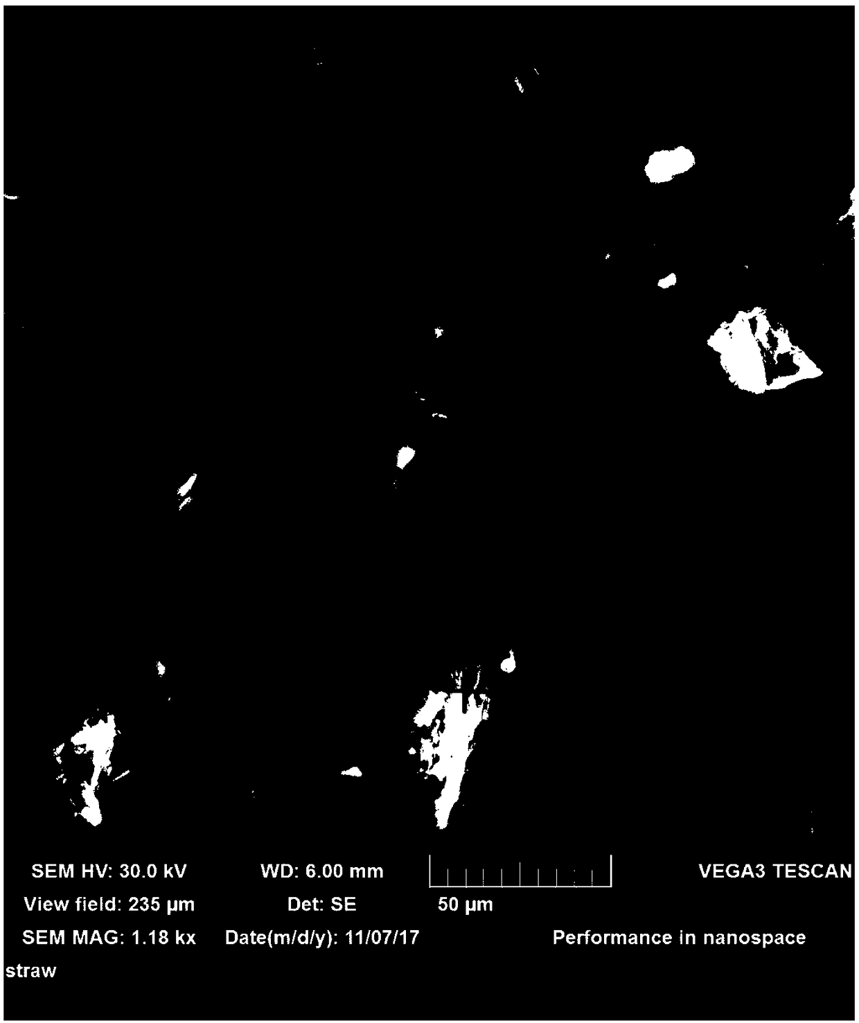
[0027] Example 1: The biomass fuel in this example is rice straw; after crushing, pass through a 200-mesh sieve, take 50g of powder under the sieve as a sample, put the sample in a ceramic boat and put it in a tube furnace for combustion in a stacked manner, In the experiment, the tube furnace was placed in a closed room of 4m*3m*3m, and the PM2.5 detection used a large flow sampler (TH-1000, flow rate 1.05m3 min-1, Wuhan Tianhong) equipped with a PM2. cutting head, and the combustion The generated soot particles were collected on the quartz filter membrane (Pallflex 2500QAT-UP, 8X10inch); the sampling pump was turned on at the beginning of the combustion, and the sampling was continued for 40 minutes until the raw material was taken out to cool down to collect the emitted soot particles as much as possible; before each combustion experiment, Pump air for 30 minutes to reduce laboratory background interference; after the filter membrane is dried in an incubator, weigh the net m...

Embodiment 2

[0045] Embodiment 2: The biomass fuel of this embodiment is corn cob, PM2.5 emission factor is bigger (1090.2 ± 605.5mg / kg), pyrolysis gas output is smaller, biomass carbon content is larger, suitable as smoldering fuel ; The milling, sampling, heating and cooling method of the present embodiment are identical with the embodiment;

[0046] A method for reducing particulate matter (PM2.5) emission factors in biomass fuels, the specific steps are as follows:

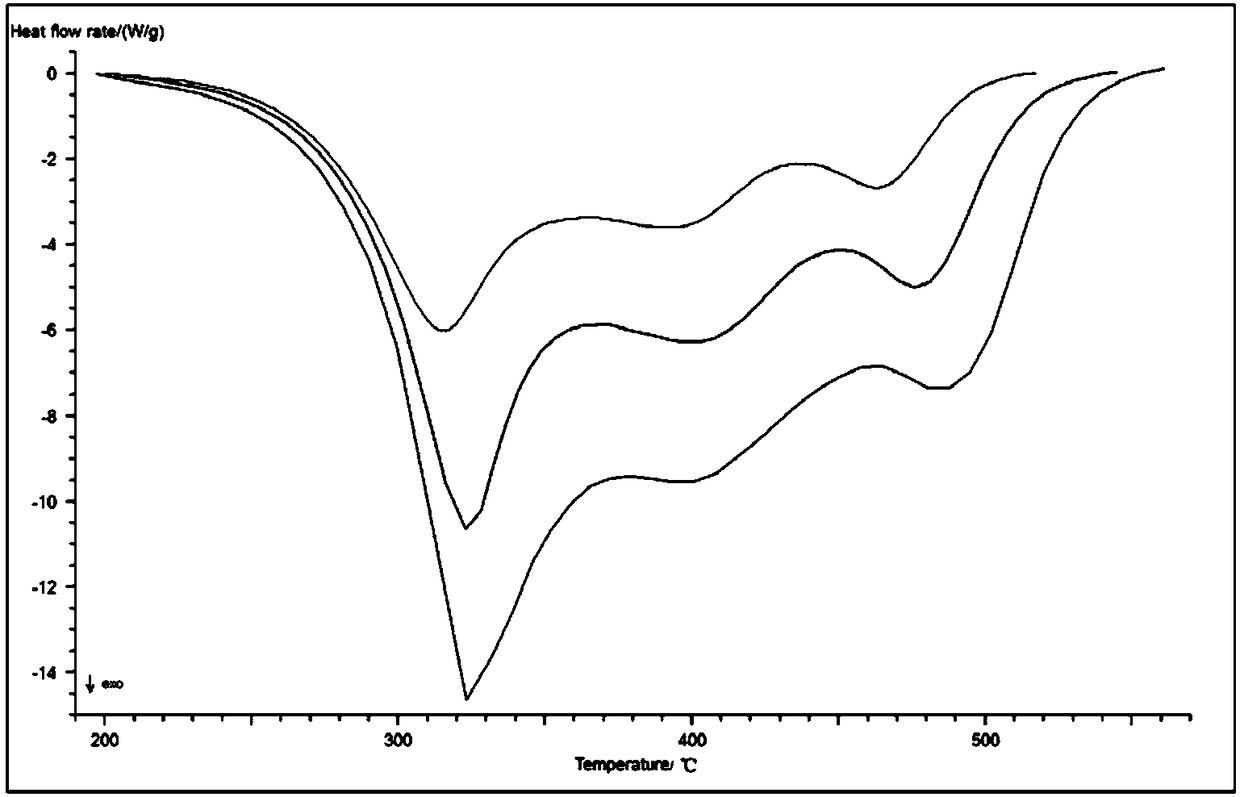
[0047] (1) According to the thermodynamic analysis data of biomass fuel combustion, that is, the differential scanning calorimetry data, the Ozawa-Flynn-Wall kinetic analysis method is used to calculate the Arrhenius formula at the temperature from 200 ° C to the combustion temperature Activation energy value;

[0048] Ozawa-Flynn-Wall kinetic analysis method for reaction process α t The initial value is 0, and the reaction is 1 when the reaction is completed. At any time in the reaction, t is calculated according to the...


PUM


Abstract

The invention discloses a method for reducing the emission factor of fine particulate matters in a biomass fuel, belonging to the technical field of energy and environmental system engineering. The method comprises the following steps: according to the differential scanning calorimetric data of biomass combustion, calculating activation energy in the Arrhenius formula during air combustion by using an Ozawa-Flynn-Wall dynamic analysis method; drawing a changing curve of the value of the activation energy and reaction course, then drawing a first-order derivative curve of the activation energyand dividing combustion phases including a large-quantity PM2.5 release phase and a small-quantity PM2.5 release phase, wherein when the changing peak value of the differential scanning curve is greater than 20% of the total amplitude or an obvious abrupt-change peak occurs in the first-order derivative curve, a new combustion stage begins; and according to the divided combustion stages of the biomass fuel, heating the biomass fuel in an oxidizing atmosphere, and carrying out cooling after completion of the large-quantity PM2.5 release phase and before starting of the small-quantity PM2.5 release phase, terminating the combustion process of the biomass fuel and carrying out cooling so as to obtain the biomass fuel with a low PM2.5 emission factor.

Description

technical field [0001] The invention relates to a method for reducing the emission factor of fine particles in biomass fuel, and belongs to the technical field of energy and environmental system engineering. Background technique [0002] Organic carbon, carbon black, and dust (ash) in the chemical composition of PM2.5 belong to primary particulate matter and are called primary particulate matter. Dust mainly comes from road traffic, construction sites, waste incineration, open-air barbecue, straw incineration, and residents' firewood burning. Among the various sources of primary particulate matter, the proportion of PM2.5 varies greatly. Road dust and construction dust are dominated by coarse particles, while particulate matter produced by fuel combustion is dominated by fine particle PM2.5. Cheng et al. (2013) calculated that from 1996 to 2010, the contribution rates of biomass burning to organic carbon (OC) and elemental carbon (EC) in PM2.5 in my country were 34%-45% and...

Claims


Application Information

Patent Timeline
IPC IPC(8): C10L5/44
CPCC10L5/445Y02E50/10Y02E50/30
Inventor 王宇栋袁聪聪施锦杨斌戴永年
Owner KUNMING UNIV OF SCI & TECH
Features
  • R&D
  • Intellectual Property
  • Life Sciences
  • Materials
  • Tech Scout
  • Unparalleled Data Quality
  • Higher Quality Content
  • 60% Fewer Hallucinations
Learn More