Draft tube as well as making method and material thereof

A guide tube and ceramic material technology, applied in the field of thermal field parts, can solve the problem that the graphite material cannot meet the design requirements of the new single crystal furnace, the cost, strength and safety of the guide tube have no advantages, and the difficulty in forming the large-size graphite outer screen, etc. problems, to achieve the effect of improving material utilization, reducing dust pollution, and shortening delivery cycle

Pending Publication Date: 2018-06-01
SHANGHAI QI JIE CARBON MATERIALS
View PDF7 Cites 2 Cited by
  • Summary
  • Abstract
  • Description
  • Claims
  • Application Information

AI Technical Summary

Problems solved by technology

From the effect point of view, this deflector has the following disadvantages: first, graphite is a good conductor of heat, and the heat preservation effect is poor; second, graphite has low strength, is easily damaged during use, and has a short service life; 1. It is difficult to form the outer screen, and there are many consumables. Fourth, the processing is difficult and time-consuming
In this way, the strength of the graphite material can no longer meet the design requirements of the new single crystal furnace. At the same time, the cost of manufacturing the guide tube with the whole graphite material is also very high, especially the larger the size, the higher the raw material cost of the graphite itself. Processing of bulk graphite raw materials, the cost will become very high
[0006] Due to the rapid development of large-scale single crystal furnaces, the graphite guide tube has no advantages in terms of cost or strength and safety. Patent No. 201420323003.4 discloses a heat shield for single crystal furnaces. Although this The manufacturing method relatively solves the problem of high cost of manufacturing the guide tube by the integral method, but the guide tube manufactured by this method also has the following problems:
[0007] 1. Too much weight;
[0008] 2. Insufficient strength;
[0009] 3. Poor sealing and high air leakage rate;
[0010] 4. The manufacturing process is complicated and the manufacturing cost is high;
[0011] 5. Splicing parts need to be grinded, which consumes a lot of raw materials and is not renewable
[0012] The production cycle of these processes is very long, the cost is very high, and the delivery speed is very slow, which cannot meet the needs of the current mono-crystalline market. Often, the delivery time cannot meet the demand or they are not selected due to high costs.
[0013] Therefore, the guide tube of the prior art still has a place to improve

Method used


Image

  • Draft tube as well as making method and material thereof
  • Draft tube as well as making method and material thereof
  • Draft tube as well as making method and material thereof

Examples


Embodiment Construction

[0054] Several preferred embodiments of the present invention will be described in detail below with reference to the accompanying drawings, but the present invention is not limited to these embodiments. The present invention covers any alternatives, modifications, equivalent methods and schemes made on the spirit and scope of the present invention. In order to provide the public with a thorough understanding of the present invention, specific details are set forth in the following preferred embodiments of the present invention, but those skilled in the art can fully understand the present invention without the description of these details.
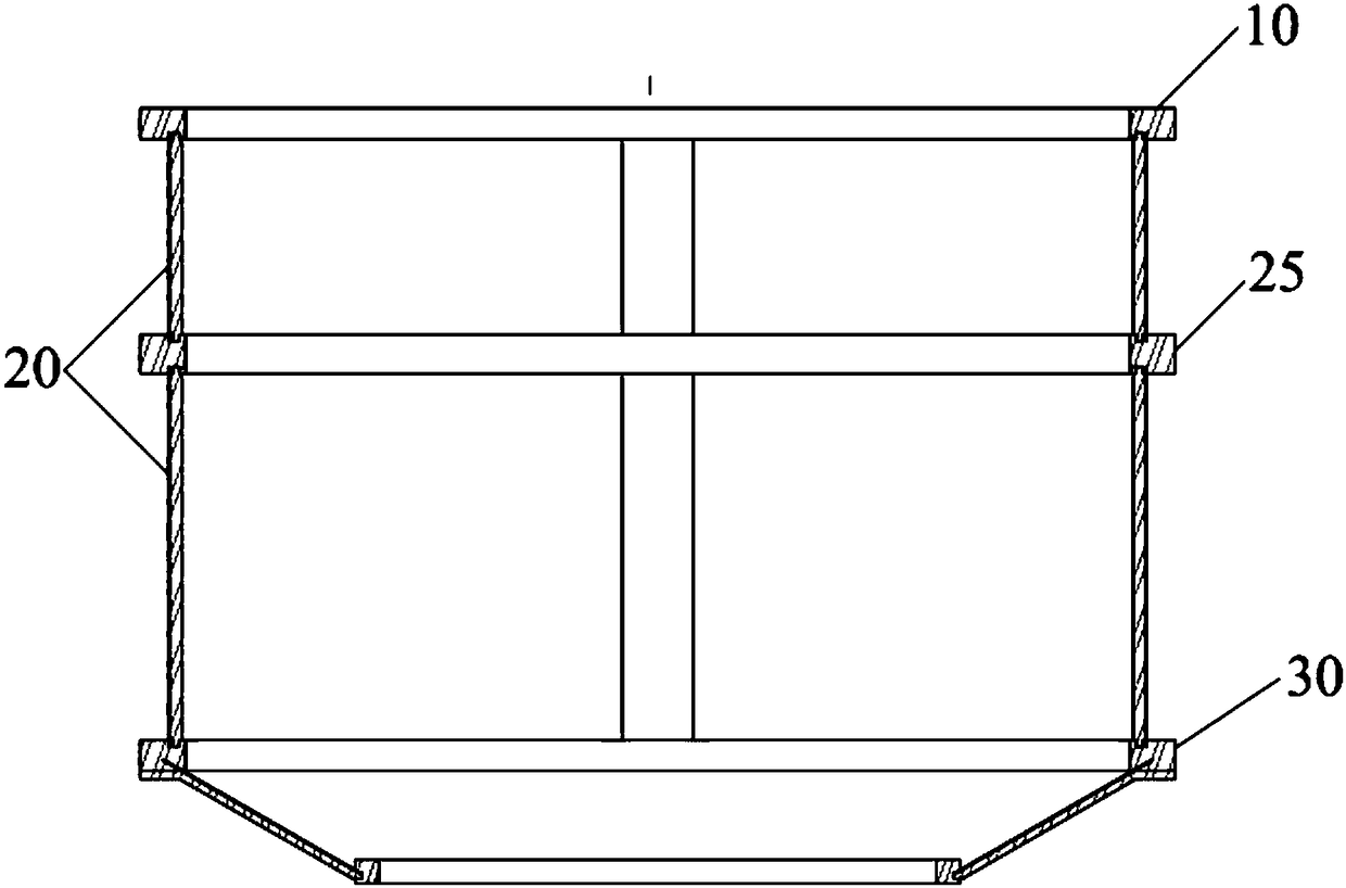
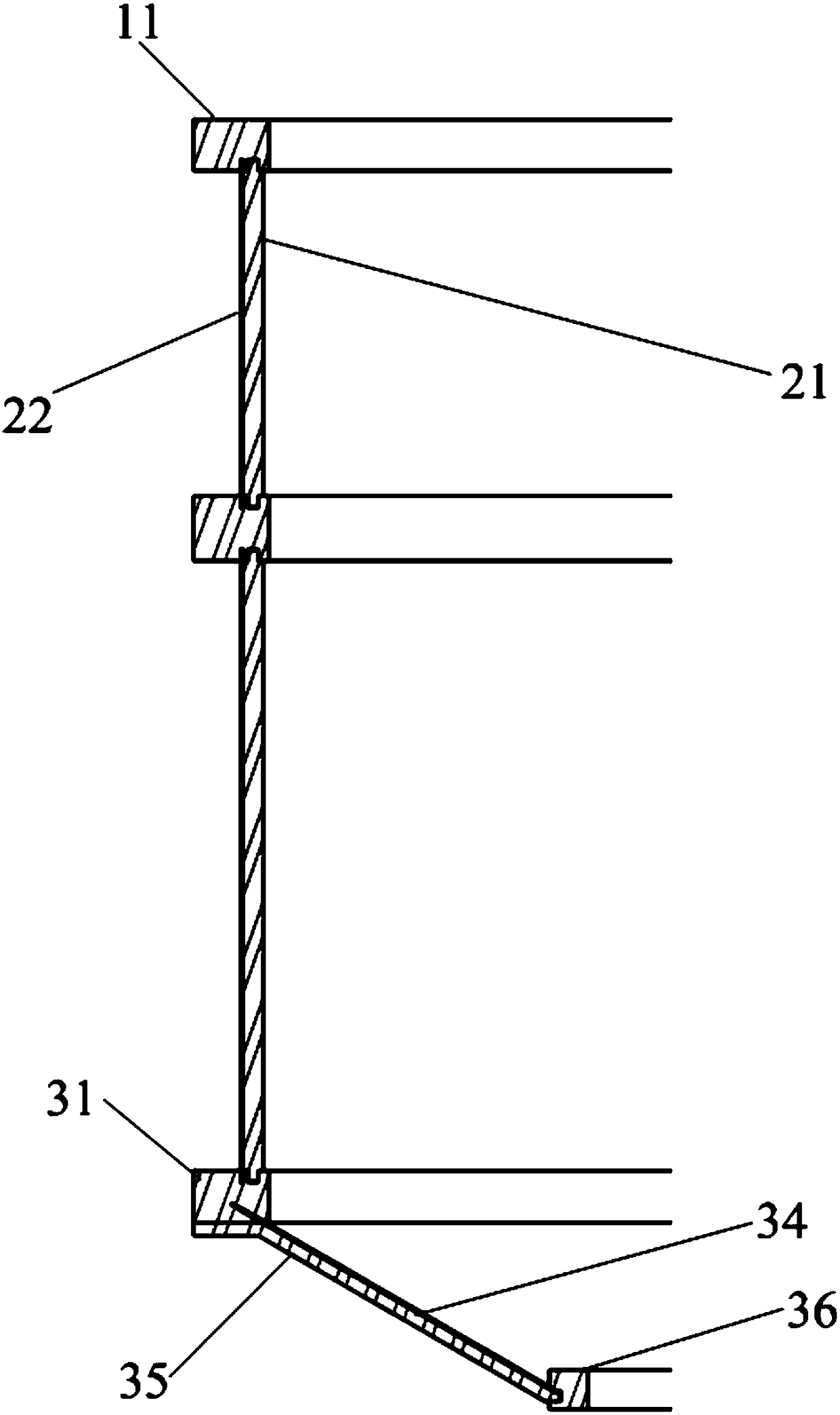
[0055] The core idea of ​​the present invention is to make a guide tube, which can effectively improve and exceed the life of the traditional guide tube. It is made of an assembled structure and designed in sections. There is no need to remake the embryo body, which can effectively save costs and shorten the delivery period, and can be ma...


PUM

PropertyMeasurementUnit
thicknessaaaaaaaaaa
thicknessaaaaaaaaaa
densityaaaaaaaaaa

Abstract

The invention provides a draft tube. The draft tube is applied to a heat field and comprises an upper ring part, a cylinder part, N middle ring hoops, a lower ring part and at least one cylinder rib plate, wherein N is an integer larger than or equal to 0; the cylinder part is made of a flexible and bendable material. The draft tube is light in weight, high in strength, non-stripping and high in safety. A blank is not needed to be made, batch production is realized, and accordingly, the delivery period is shortened, and few materials are wasted in processing.

Description

technical field [0001] The invention relates to thermal field components, in particular to a draft tube made and assembled from carbon / carbon composite material or graphite material or high-temperature-resistant metal material or ceramic material and a preparation method thereof. Background technique [0002] In the manufacture of single crystal silicon, the Czochralski method (CZ method) is generally used at present, which is a method of pulling a single crystal from a melt along a vertical direction. In the prior art equipment, as the crystal diameter of monocrystalline silicon grows thicker and thicker, the diameter of the corresponding single crystal furnace is also larger and larger, so the reliability and safety of the thermal field are also required to be higher and higher. ; The thermal field system of the monocrystalline silicon drawing furnace has a great influence on the whole rod rate and yield, the pulling speed and the quality of the monocrystalline silicon rod...

Claims


Application Information

Patent Timeline
Patent Type & Authority Applications(China)
IPC IPC(8): C30B15/00C30B29/06
CPCC30B15/00C30B29/06
Inventor 申富强申富胜李科
Owner SHANGHAI QI JIE CARBON MATERIALS
Why Eureka
Try Eureka