
Electroplating equipment and electroplating method for foam metal material

A technology of metal foam and electroplating equipment, applied in the direction of electrodes, etc., can solve the problems affecting the plated products (conductive sponge metal plating amount, increase the difficulty of unblocking pipelines, and high resistance of conductive sponges, etc., so as to increase the utilization rate of anodes and reduce product defects. The effect of reducing the efficiency and reducing the energy consumption of electroplating

Active Publication Date: 2018-06-22
CHANGDE LYRUN MATERIAL
View PDF5 Cites 5 Cited by
  • Summary
  • Abstract
  • Description
  • Claims
  • Application Information

AI Technical Summary

Problems solved by technology

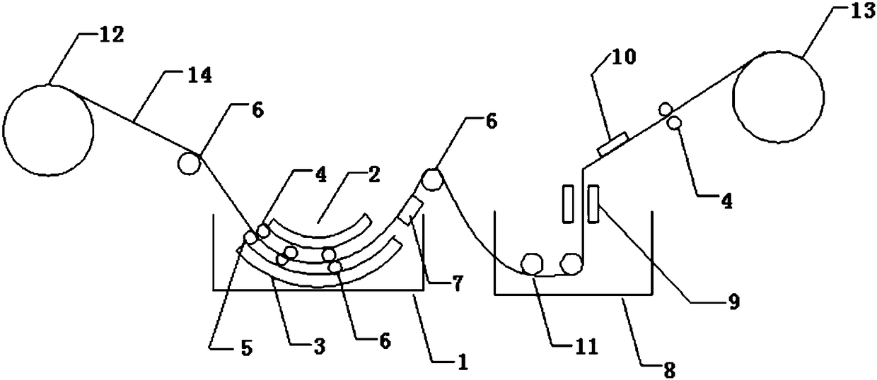
[0003] Due to the large resistance of the conductive sponge, the conductivity is not good. In the prior art, the conductive area of ​​the cathode is increased by increasing the use of a pre-plating roller (that is, a large conductive cylinder), and the conductivity of the cathode is increased to improve the poor conductivity and the low amount of conductive metal. The resistance of the substrate is high, but because the pre-plating roller is immersed in the solution for a long time under conductive conditions, a large amount of plating metal is deposited on the pre-plating roller, which affects the metal plating amount of the plated product (conductive sponge)
When the amount of metal deposition on the surface of the pre-plating roller reaches a certain level, the metal layer bursts due to the stress release of the metal layer caused by the curved surface (in the form of large or small pieces of metal fragments), thereby cutting or hooking the product, and the plating If the metal layer falls into the solution or product, it will cause foreign matter to adhere to the product, and the debris will block the pipeline, making it difficult to dredge the pipeline

Method used


Image

  • Electroplating equipment and electroplating method for foam metal material
  • Electroplating equipment and electroplating method for foam metal material

Examples


Embodiment 1

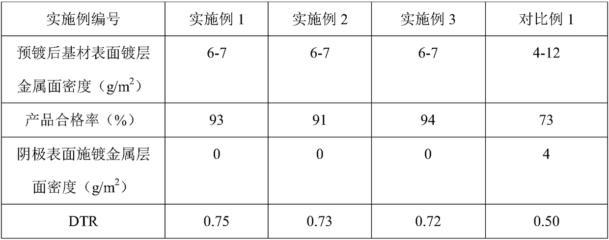
[0042]Adopt the equipment of the present invention, the 1.4mm thick that has been conductively treated, the polyurethane sponge of 110ppi hole number enters in the pre-plating tank through the unwinding machine through the guide roller and the driving roller, and interacts with the driving roller through the hydraulic roller before the pre-plating Squeeze out the internal air, the two anodes distributed up and down provide electroplating cations, and the cathode above the pre-plating solution is powered. The pre-plating solution is Watts plating solution, in which the total nickel is 75-85g / L, and the nickel chloride is 60- 70g / L, boric acid 30-40g / L, bath pH 4.3-4.6, temperature 55°C, pre-plating current 40A, substrate speed 0.1m / min, pre-plating time 2min. The pre-plating foam substrate is subjected to main plating, the composition of the main plating solution is the same as that of the pre-plating solution, the pH value is 4.3-4.6, the temperature is 55°C, the main plating c...

Embodiment 2

[0044] Adopt the equipment of the present invention, with the polyester sponge of 1.0mm thickness that has been conductively treated, the number of holes of 120ppi, enter in the pre-plating tank through the unwinder through the guide roller and the driving roller, and pass the hydraulic pressure roller and the driving roller to interact with each other before the pre-plating. Squeeze out the internal air, the two anodes distributed up and down provide electroplating cations, and the cathode above the pre-plating solution is powered. The pre-plating solution is Watts plating solution, of which the total nickel is 75-85g / L, and the nickel chloride is 60 -70g / L, boric acid 30-40g / L, bath pH 4.3-4.6, temperature 55°C, pre-plating current 50A, substrate speed 0.13m / min, pre-plating time 1.5min. The pre-plating foam substrate is subjected to main plating, the composition of the main plating solution is the same as that of the pre-plating solution, the pH value is 4.3-4.6, the tempera...

Embodiment 3

[0046] Adopt the equipment of the present invention, with the polyether sponge of 1.6mm thickness that has been conductively treated, 95ppi hole number, enter in the pre-plating tank through the unwinder through the guide roller and the driving roller, and pass the hydraulic pressure roller and the driving roller before the pre-plating. Squeeze out the internal air, the two anodes distributed up and down provide electroplating cations, and the cathode above the pre-plating solution is powered. The pre-plating solution is Watts plating solution, of which the total nickel is 75-85g / L, and the nickel chloride is 60 -70g / L, boric acid 30-40g / L, bath pH 4.3-4.6, temperature 55°C, pre-plating current 40A, substrate speed 0.1m / min, pre-plating time 2min. The pre-plating foam substrate is subjected to main plating, the composition of the main plating solution is the same as that of the pre-plating solution, the pH value is 4.3-4.6, the temperature is 55°C, the main plating current is 1...


PUM


Abstract

The invention discloses electroplating equipment and electroplating method for a foam metal material. The electroplating equipment comprises an unrolling device, a pre-plating slot, an electroplatingslot and a rolling device, wherein the pre-plating slot comprises a pre-plating slot body, an anode I and an anode II which are distributed up and down in the pre-plating slot body, and a cathode plate I arranged above the pre-plating liquid level; the anode I and the anode II are in an arc shape; and arc length of the anode I is smaller than that of the anode II. The electroplating method comprises the following steps of extruding out air inside a foam base material subjected to conductive treatment before pre-plating through mutual action of a transmission roller and a hydraulic roller, providing electroplating positive ions by the anode I and the anode II, energizing a cathode, and performing primary plating and post-treatment to obtain the foam metal material. The upper and lower anodes are arranged in the pre-plating slot, and thickness of metal plated on front and back surfaces of the base material is more uniform. The cathode in the pre-plating slot body is not soaked into pre-plating liquid, and metal is not deposited or plated on the surface of the cathode, so that a product qualification rate is 90% or more, and a cathode utilization rate is increased.

Description

technical field [0001] The invention belongs to the technical field of electroplating, and in particular relates to electroplating equipment and an electroplating method for foam metal materials. Background technique [0002] Traditional engineering believes that the existence of holes in metal materials is often the core of the formation and expansion of microcracks in materials, which will adversely affect the physical, chemical and mechanical properties of materials. But when the number of holes in the material reaches a certain level and the distribution is uniform, the various properties of the material are greatly improved, which is the metal foam material. Foam metal material is a composite material composed of metal matrix and holes. Due to the large number of holes in the material, compared with solid metal materials, it has low density, large specific surface area, high specific strength, excellent permeability, and good electromagnetic shielding performance. , go...

Claims


Application Information

Patent Timeline
Patent Type & Authority Applications(China)
IPC IPC(8): C25D5/56C25D3/12C25D19/00C25D17/12C25D7/06
CPCC25D3/12C25D5/56C25D7/0642C25D7/0657C25D17/12
Inventor 彭为林峰熊轶智蒋素斌
Owner CHANGDE LYRUN MATERIAL
Learn More