
Ultrahigh-speed laser cladding system

A laser cladding and ultra-high-speed technology, applied in metal material coating process, coating and other directions, can solve the problems of low powder utilization rate, large heat input, large heat influence, etc., and achieve high interface bonding strength and heat input The effect of small quantity and waste reduction

Inactive Publication Date: 2018-06-29
ADVANCED MFG TECH CENT CHINA ACAD OF MASCH SCI & TECH
View PDF1 Cites 19 Cited by
  • Summary
  • Abstract
  • Description
  • Claims
  • Application Information

AI Technical Summary

Problems solved by technology

Due to the large number of pores in the coating prepared by thermal spraying, it must be prepared by multi-layer deposition (each layer is about 25-50 μm thick), resulting in reduced processing efficiency
In addition, the consumption of powder materials and gas in the processing process is relatively large, and the maximum utilization rate of materials is only about 50%.
[0005] 3. Overlay welding technology. The coating of this technology is generally thicker (about 2~3mm), but the parts need to be preheated, the heat input is large, and the heat-affected zone is large, resulting in large deformation of the parts and a decline in mechanical properties.
[0006] 4. Laser cladding technology, see figure 2 , this traditional technology has the advantages of high bonding strength, small heat quantity, small deformation, etc., and can obtain the required cladding layer properties by adjusting the powder composition, so it has begun to be applied in many industries, but the processing efficiency of this technology is low. The cladding rate is generally 0.5~3m / min, the powder utilization rate is low, generally about 50%, and the laser energy is focused on the matrix material, and the powder is mixed and bonded by melting the matrix material, which makes the laser energy utilization efficiency and cladding The rate is low, the powder is still a solid particle when combined with the base material, and the surface smoothness of the finished product is poor

Method used


Image

  • Ultrahigh-speed laser cladding system
  • Ultrahigh-speed laser cladding system
  • Ultrahigh-speed laser cladding system

Examples


Embodiment 1

[0037] Preferably, the present invention discloses an ultra-high-speed laser cladding system. The system preferably includes:

[0038] Ultra-high-speed laser cladding processing machine tool for clamping tooling parts through a chuck;

[0039] Adjustable ultra-high speed laser cladding head;

[0040] Powder feeding head

[0041] A control unit connected to the machine tool, the adjustable ultra-high-speed laser cladding head and the powder feeding head; and

[0042] The parameter storage unit, which is connected to the control unit, is used to store the working parameters of the machine tool, the adjustable ultra-high-speed laser cladding head and the powder feeding head;

[0043] Among them, the control unit can adjust the laser defocus of the laser cladding head to 1~2mm and the spot size Φ1.0~Φ1.5mm according to the parameters stored in the parameter storage unit, and adjust the X axis of the machine tool (workpiece radial direction) to feed powder The distance between the head and ...

Embodiment 2

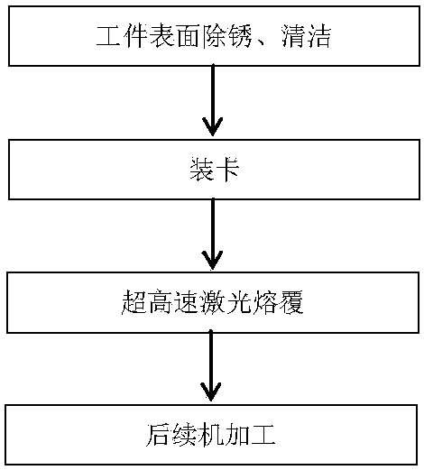
[0056] See figure 1 , The present invention also provides an ultra-high-speed laser cladding method, which specifically adopts the following steps:

[0057] (1) Wipe and clean the rust spots on the surface of the workpiece to be cladding with sandpaper, and clean it with alcohol;

[0058] (2) Load the workpiece into the ultra-high-speed laser cladding processing machine tool, and clamp it by the chuck;

[0059] (3) Adopt ultra-high-speed laser cladding alloy powder as cladding material;

[0060] (4) Adjust the Z direction knob of the laser cladding head, set the laser defocus amount to 1~2mm, and the spot size Φ1.0~Φ1.5mm; adjust the X axis of the machine tool (radial of the workpiece) so that the powder feeding head is 10~13mm away from the surface of the workpiece , The powder focal point is 0.2~2mm away from the surface of the workpiece, and the powder spot size is Φ0.5~1mm;

[0061] (5) Adjust the speed of the powder feeding tray of the powder feeder to control the powder feeding ...

Embodiment 3

[0071] The present invention also provides an ultra-high-speed laser cladding method, which is characterized by comprising the following steps:

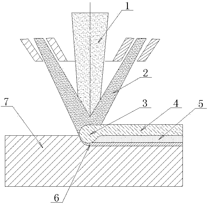
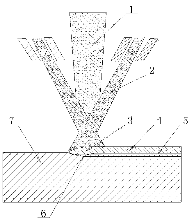
[0072] Control a small part of the energy of the laser to act on the upper surface of the base material to form a shallow molten pool 3, and most of the laser energy acts on the alloy powder above the base material;

[0073] The temperature of the alloy powder rises to the melting point and melts before entering the molten pool 3, and is dropped into the molten pool 3 in the form of droplets to be combined with the matrix material.

[0074] It is understandable that since the traditional methods focus the laser energy on the matrix material to melt the dense matrix itself, under the same laser energy, the time it takes to melt the matrix needs to be greatly increased, which greatly limits The cladding speed reduces the utilization rate of the powder. On the contrary, in the present invention, the laser energy is skillfully applied to the al...


PUM

PropertyMeasurementUnit
sizeaaaaaaaaaa
oxygen contentaaaaaaaaaa
fluidityaaaaaaaaaa

Abstract

The invention belongs to the field of laser processing, and specifically provides an ultrahigh-speed laser cladding system. The system is characterized in that ultrahigh-speed laser cladding linearityspeed can be realized when a workpiece rotates at a high speed; laser and powder mutually act, and the system parameters are adjusted and matched, thus a dense cladding layer can be formed on the surface of the workpiece. Compared with a traditional laser cladding system, the ultrahigh-speed laser cladding system has the advantages that the laser cladding efficiency is improved dozens of times, and moreover, the obtained cladding layer is of a completely metallurgical combination form; the surface smoothness is high; the material utilization rate is high; the energy consumption is low; the production cost can be extremely saved; and the production efficiency is improved.

Description

Technical field [0001] The invention relates to an ultra-high-speed laser cladding system and method, belonging to the field of laser processing. Background technique [0002] In the field of construction machinery, many shaft metal components have requirements for corrosion resistance and wear resistance on the surface, and require special treatment. Common treatment systems include the following types. [0003] 1. Electroplating technology. The coating of this technology is thin, generally no more than 100μm. Therefore, it is easy for the entire part to fail due to damage to the partial coating under special conditions. Moreover, the bonding force between the coating and the substrate is weak, generally not exceeding 100MPa, and the corrosion resistance is poor, and it is easy to peel off. It also causes serious waste of resources and environmental pollution, which is an industry that urgently needs to be relieved. [0004] 2. Thermal spraying technology. This technology is mecha...

Claims


Application Information

Patent Timeline
Patent Type & Authority Applications(China)
IPC IPC(8): C23C24/10
CPCC23C24/103
Inventor 王淼辉葛学元郭瑞峰
Owner ADVANCED MFG TECH CENT CHINA ACAD OF MASCH SCI & TECH
Features
  • Generate Ideas
  • Intellectual Property
  • Life Sciences
  • Materials
  • Tech Scout
  • Unparalleled Data Quality
  • Higher Quality Content
  • 60% Fewer Hallucinations
Learn More