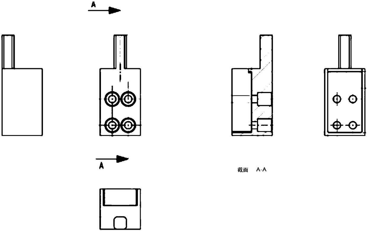
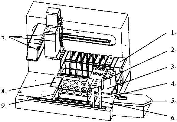
Mechanical arm separation module
A separation module and robotic arm technology, applied in the preparation of test samples, etc., can solve the problems of long sample separation time, short instrument life, corrosion damage to instrument parts, etc., to avoid the risk of cross-contamination, improve the accuracy of liquid collection, The effect of improving separation efficiency
- Summary
- Abstract
- Description
- Claims
- Application Information
AI Technical Summary
Problems solved by technology
Method used
Image

Examples
Embodiment 1
[0076] In this example, the above-mentioned experimental equipment and collection mode 1 were used for experimental operation, and the specific parameters were: the sample contained 61g / L U, 1.0×10 -4 g / L Np, 4×10 -7 g / L Pu and 3mol / L HNO 3 , the reagent is HNO 3 、HON 3 -HF and H 2 C 2 o 4 、H 2 O. The specific steps are as follows:
[0077] (1) Take 1ml of sample, add 0.2ml ferrous sulfamate reducing agent and put it into the sample bottle, place the sample bottle on the sample bottle holder;
[0078] (2) Turn on the device, start the separation software, and the software running program is:
[0079] a pretreatment with 5ml HNO 3 Add to the extraction column 1 at a flow rate of 1mi / min, and wait for 4 seconds;
[0080] b Adding samples Add 2ml of sample into the extraction column 1 at a flow rate of 1ml / min, and wait for 4 seconds;
[0081] c rinse with 10ml HNO 3 Add to the extraction column 1 at a flow rate of 1ml / min, and wait for 4 seconds;
[0082] d Elution ...
Embodiment 2
[0095] In this embodiment, the above-mentioned experimental equipment and collection mode 3 are used for experimental operation. The specific parameters are: the sample is 16.2ng / ml plutonium solution (3M nitric acid system), and the reagent is HNO 3 、HON 3 -HF and H 2 O. Specific steps are as follows:
[0096] (1) Take 0.3ml of sample in a 5ml sample bottle, add 0.1ml of 0.5M ferrous sulfamate, shake slightly evenly, and place it in the sample position of the sample bottle holder;
[0097] (2) Turn on the device, start the separation software, and the software running program is:
[0098] a pretreatment with 5ml HNO 3 Add to the extraction column 1 at a flow rate of 1mi / min, and wait for 4 seconds;
[0099] b Adding samples Add 2ml of sample into the extraction column 1 at a flow rate of 1ml / min, and wait for 4 seconds;
[0100] c Elution with 1ml HNO 3 - HF is added to the extraction column 1 at a flow rate of 1ml / min, the collection tube is at position 1, and wait fo...
PUM
 Abstract
Description
Claims
Application Information
 - R&D
- Intellectual Property
- Life Sciences
- Materials
- Tech Scout
- Unparalleled Data Quality
- Higher Quality Content
- 60% Fewer Hallucinations
Browse by: Latest US Patents, China's latest patents, Technical Efficacy Thesaurus, Application Domain, Technology Topic, Popular Technical Reports.
© 2025 PatSnap. All rights reserved.Legal|Privacy policy|Modern Slavery Act Transparency Statement|Sitemap|About US| Contact US: help@patsnap.com