Mine ultrasonic rock breaking equipment
A kind of rock breaking equipment, ultrasonic technology, applied in the direction of borehole/well parts, drilling with vibration, earthwork drilling and mining, etc., can solve the problems of high pollution, high consumption, low efficiency, etc., and achieve reduced dust concentration, low noise level, The effect of less energy consumption
- Summary
- Abstract
- Description
- Claims
- Application Information
AI Technical Summary
Problems solved by technology
Method used
Image
Examples
Embodiment 1
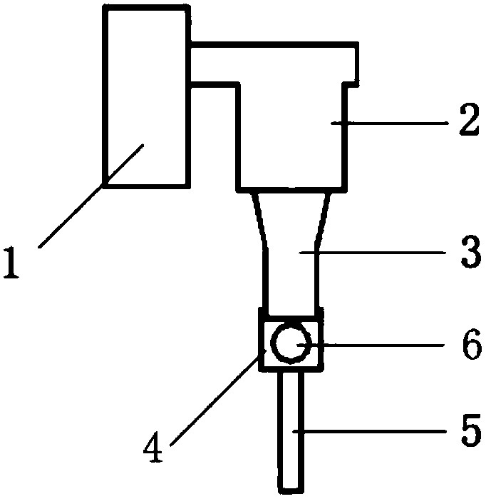
[0025] Such as figure 1 As shown, a mine ultrasonic rock breaking equipment includes an ultrasonic generator 1 , an ultrasonic transducer 2 , a horn 3 , a hollow connector 4 , an ultrasonic drill pipe 5 , and a sphere 6 . The ultrasonic generator 1 is connected to the ultrasonic transducer 2, the end of the ultrasonic drill rod 5 is fixed on the front end of the horn 3, the two ends of the hollow connector 4 are connected to the front end of the horn 3 and the end of the ultrasonic drill rod 5, and the spherical 6 can vibrate back and forth in the hollow connecting member 4 along the direction from the front end of the horn 3 to the end of the ultrasonic drill rod 5 . When in use, the ultrasonic generator 1 converts commercial power into a high-frequency alternating current signal matched with the ultrasonic transducer 2 to drive the ultrasonic transducer 2 to work. Driven by the ultrasonic generator 1, the ultrasonic transducer 2 converts the input electric energy into longi...
Embodiment 2
[0027] Such as figure 2 As shown, an ultrasonic drilling and rock breaking equipment includes a connecting nut 8 between drill rods, a power supply wire 9, an ultrasonic drilling rig base 10, an ultrasonic generator 1, a connecting ring 11, an ultrasonic transducer 2, a horn 3, and a drill rod 12. Hollow connector 4, ultrasonic drill pipe 5, sphere 6, connecting rod 7, drill bit 13, water injection nozzle 14. The ultrasonic generator 1 and the ultrasonic transducer 2 are located in the middle of the drill pipe 12, the end of the horn 3 is located at the front of the drill pipe 12, and the front end of the horn 3 passes through the front end of the drill pipe 12 and extends into the drill bit 13. The end of the drill pipe 5 is located inside the drill bit 13 and is connected to the front end of the horn 3, the front end of the ultrasonic drill pipe 5 passes through the top of the drill bit 13, the water injection nozzle 14 is located at the top of the drill bit 13, and the wat...
Embodiment 3
[0051] Such as Figure 4 As shown, a top-coal ultrasonic weakening equipment includes a hydraulic support shield beam 15, a hydraulic support top beam 16, a water injection nozzle 17 and the mine ultrasonic rock breaking equipment 18 in Example 1. The end of hydraulic support shield beam 15 and hydraulic support top beam 16 mine ultrasonic rock breaking equipment 18 is fixed on the front end of hydraulic support top beam 16, and water injection nozzle 17 is fixed on the front end side wall of hydraulic support top beam 16. The water injection direction of the water injection nozzle 17 is towards the front end of the mine ultrasonic rock breaking equipment 18 . When using the top coal ultrasonic weakening equipment to drill holes, the water injection nozzle 17 sprays water to the front end of the mine ultrasonic rock breaking equipment 18 . The propagation of ultrasonic waves in water produces cavitation, and the rock surface is deformed and eroded after being impacted by cavi...
PUM
 Abstract
Description
Claims
Application Information
 - R&D
- Intellectual Property
- Life Sciences
- Materials
- Tech Scout
- Unparalleled Data Quality
- Higher Quality Content
- 60% Fewer Hallucinations
Browse by: Latest US Patents, China's latest patents, Technical Efficacy Thesaurus, Application Domain, Technology Topic, Popular Technical Reports.
© 2025 PatSnap. All rights reserved.Legal|Privacy policy|Modern Slavery Act Transparency Statement|Sitemap|About US| Contact US: help@patsnap.com


