Supercharge Your Innovation With Domain-Expert AI Agents!

Electromagnetic resonance inertial damper

A resonant damper technology, which is applied in the field of electromagnetic resonance inertial dampers, can solve the problems of limited range of changing magnetic field strength, limited adaptability of dampers, and low sensitivity of vibration switches, so as to achieve optimal vibration reduction effect and structural reduction. Excellent vibration control performance, life stiffness and damping controllable effect

Active Publication Date: 2022-05-10
HUNAN UNIV OF SCI & TECH
View PDF12 Cites 0 Cited by
  • Summary
  • Abstract
  • Description
  • Claims
  • Application Information

AI Technical Summary

Problems solved by technology

For example, the patent number 201610644195.2, the authorization number CN106015420A, the name is "a semi-active vibration control eddy current damper", which is composed of an eddy current energy consumption module, an automatic control module, a magnetic field shield, a buffer spring and various connecting parts. Semi-active control with variable damping, but the range of changing the magnetic field strength is limited, there are certain problems in damping adjustment, and the sensitivity of the vibration switch is not high, which affects the vibration damping performance; patent number 201310422426.1, authorization number CN103470676 A, the name is "Inertial mass energy storage vibration damping device with parallel damper", a traditional vibration isolator composed of springs and dampers connected in parallel, and a new type of vibration isolator composed of inertial mass accumulators and dampers connected in parallel, and then connected in series with springs. The mass energy storage vibration damping device is composed of a traditional vibration isolator and a new vibration isolator in parallel, which can greatly improve the vibration characteristics of the suspended mass under the condition that the working space of the vibration damping device remains unchanged, so that the overall vibration damping device The performance has been greatly improved, but because the spring and damping characteristics of the damper do not change with time, the adaptability of the damper to various frequencies and forms of external excitation is limited; patent number 201110443539.0, authorization number CN102493572A, named "a An adjustable damping energy storage type tuned mass damper", the damping adjustment device of the damper is composed of a permanent magnet, a coil, an auxiliary rod, an energy storage battery, an adjustable resistor, and an LED warning indicator light. Adjust the resistance, thereby changing the size of the electromagnetic damping, so that the damping ratio of the structure reaches the optimal damping ratio, and use the energy storage battery to recover excess energy, but because the damper cannot adapt to various frequencies and forms of external excitation, it is easy to cause The damper cannot adjust the frequency, which affects the damping effect of the damper; patent number 201510589913.6, authorization number CN105221622A, named "Variable Rotation Equivalent Inertial Mass Damper", which consists of energy dissipation elements, translation / rotation conversion devices, speed change devices, secondary Consisting of energy-consuming components, rotating masses, control chips and circuits, etc., the optimal value of equivalent inertial mass and viscous damping can be adjusted in real time, and at the same time, part of the vibration energy can be harvested and stored. However, due to the magnetic Rheological fluid is the main energy-consuming material of the damper. After long-term operation, the mechanical properties will degrade; It consists of magnetically conductive metal particles filled in the hollow steel pipe of the truss structure, a coil wound on the outer wall of the hollow steel pipe, a current control module connected to the coil, a vibration pickup sensor set on the damped structure, and a DC power supply module to realize In order to track the vibration frequency of the structure to be damped and quickly adjust the optimal damping ratio of the particle damper, thereby improving its vibration reduction performance in a wider frequency band, but the use of this semi-active particle damper is limited. Insensitive to low frequency vibration
It is particularly worth noting that in the current control technology, there is no comprehensive use of electromagnetic tuning resonant circuit RLC, electromagnetic energy consumption and inertia, and self-powered semi-active control in the damper device.

Method used


Image

  • Electromagnetic resonance inertial damper

Examples


Embodiment Construction

[0017] specific implementation

[0018] The present invention will be further described below in conjunction with the accompanying drawings and embodiments.

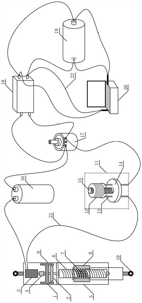
[0019] Such as figure 1 As shown, the present invention comprises a ball screw mechanism 5, a gearbox 2, a rotating flywheel 1 and a generator 3, the generator 3 and the gearbox 2 are installed in the tailpiece 9, the input shaft of the generator 3 and the output shaft of the gearbox 2 Connection; the input shaft of the gearbox 2 is connected with the upper end of the rotating flywheel 1, and the lower end of the rotating flywheel 1 is connected with the leading screw of the ball screw mechanism 5; the nut of the ball screw mechanism 5 is connected with the upper end of the connector 10. The output terminal of generator 3 is connected with the resistance-inductance-capacitance RLC series resonant circuit, and the resistance-inductance-capacitance RLC series resonant circuit is connected with the input terminal of the vo...


PUM


Abstract

The invention discloses an electromagnetic resonance inertial mass damper, which comprises a tailpiece, a ball screw mechanism, a gearbox, a rotating flywheel, a generator and a battery; One end is connected, and the other end of the flywheel is connected to the lead screw of the ball screw mechanism; the nut of the ball screw mechanism is connected to the connecting piece; the output end of the generator is connected to a resistance-inductance-capacitance RLC series resonant circuit, resistance-inductance-capacitance The RLC series resonant circuit is connected with the regulated current device, and the regulated current device is connected with the battery; the battery output terminal is connected with the self-powered semi-active controller module through the wire, and the self-powered semi-active controller module is connected with the regulated current device through the signal line connect. The invention has the characteristics of high power generation efficiency, non-contact, no mechanical friction and wear, no lubrication, long life, and controllable stiffness and damping; and can convert structural vibration mechanical energy into electrical energy and collect vibration energy.

Description

technical field [0001] The invention belongs to the technical field of dampers, in particular to an electromagnetic resonance type inertial damper. Background technique [0002] Civil engineering structures are prone to large vibrations under external effects such as strong winds, rainstorms, and earthquakes in the natural environment, which increases structural damage, affects the safety and comfort of the structure, and reduces the service life of the structure. How to reduce the response of structures due to external dynamic loads has become a hot research topic for scholars at home and abroad. So far, domestic and foreign scholars have researched and developed many structural control technologies, which can be divided into passive control, active control, semi-active control and hybrid control according to whether the control measures adopted require external energy. Structural passive control is a structural control technology that does not require external energy. It ...

Claims


Application Information

Patent Timeline
Patent Type & Authority Patents(China)
IPC IPC(8): E04B1/98E04H9/02
CPCE04H9/021
Inventor 孙洪鑫周璋亮王文熙禹见达牛华伟
Owner HUNAN UNIV OF SCI & TECH
Features
  • R&D
  • Intellectual Property
  • Life Sciences
  • Materials
  • Tech Scout
  • Unparalleled Data Quality
  • Higher Quality Content
  • 60% Fewer Hallucinations
Learn More