Glass fiber composite tube

A composite material pipe and glass fiber technology, applied in gas treatment, membrane technology, dispersed particle separation, etc., can solve the problems of difficult management, high operating cost, and low efficiency, and achieve low smoke aerosol generation and dust removal The effect of shortening the process

Inactive Publication Date: 2018-08-17
TONGXIANG ZHIYUAN ECO FRIENDLY TECH
View PDF6 Cites 0 Cited by
  • Summary
  • Abstract
  • Description
  • Claims
  • Application Information

AI Technical Summary

Problems solved by technology

[0006] The current flue gas desulfurization, denitrification and dust removal system is a simple combination of the above independent systems, with their own independent equipment and control systems. The entire desulfurization, denitrification and dust removal system has huge hardware and software and occupies a lot of space, which has large investment and difficult management. , low efficiency, high operating costs and other disadvantages

Method used


Image

  • Glass fiber composite tube
  • Glass fiber composite tube
  • Glass fiber composite tube

Examples


Embodiment 1

[0028] A glass fiber composite material pipe described in this embodiment is formed by mixing glass fiber material, catalyst and binder and then pressing and drying; wherein the catalyst accounts for 20% of the total mass of all materials.

[0029] The glass fiber material is glass fiber spun yarn; the catalyst is a denitration catalyst; the binder is a high temperature resistant inorganic binder.

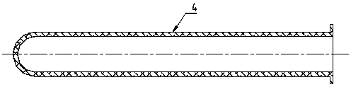
[0030] The shape of the cross-section of the glass fiber composite pipe is circular. The size of the glass fiber composite pipe is: the diameter of the circular pipe is 250mm, the thickness of the pipe wall is 25mm, and the length of the pipe is 2500mm.

[0031] The glass fiber composite material pipe is a tubular structure with one end closed.

Embodiment 2

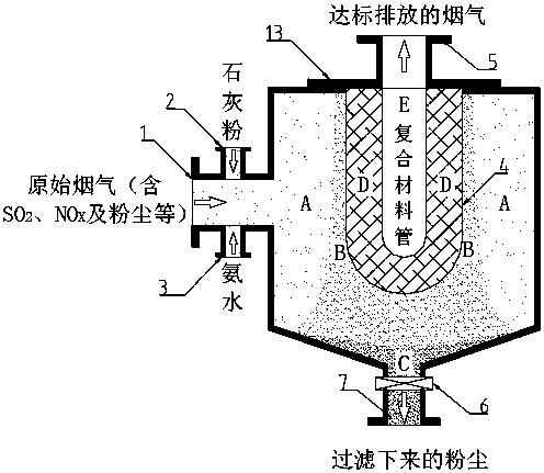
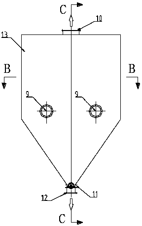
[0033] Such as image 3 , Figure 4 , Figure 5 As shown, the glass fiber composite pipe described in this embodiment has a length of 3000 mm, a diameter of 300 mm, and a wall thickness of 30 mm. it is installed in Figure 4 Among the desulfurization, denitrification and dust removal integrated devices 13, there are 5 rows, 6 in each row, 30 in total. Divided into two flue gas inlets 9, the flue gas containing sprayed lime powder and ammonia water enters the integrated device 13 from the two inlets 9, and after desulfurization, denitrification and dust removal processes, the dust is discharged from the outlet 12 through the valve 11, desulfurization and denitrification After dust removal, the flue gas that meets the emission standard is discharged from outlet 10.

[0034] Its specific working principle is as follows figure 2 As shown, the glass fiber composite pipe according to the present invention is installed inside the desulfurization, denitrification and dust remova...


PUM

PropertyMeasurementUnit
diameteraaaaaaaaaa
thicknessaaaaaaaaaa

Abstract

The invention relates to the field of industrial flue gas treatment equipment, in particular to a glass fiber composite tube. The glass fiber composite tube is obtained by mixing a glass fiber material, a catalyst and a binder and then pressing, drying and forming, wherein the catalyst accounts for 3-30% of the total mass of all the materials. The glass fiber material is one or more of glass fiberspun yarns, glass fiber rough yarns and a chopped strand mat; the catalyst is a denitration catalyst or a dioxin removing catalyst; and the binder is a high-temperature-resistant inorganic binder. The glass fiber composite tube is used in the field of flue gas treatment, a large number of tiny gaps are formed in the tube wall, gas out of the tube can enter the inside of the tube through the gaps,and meanwhile, dust with the size greater than 2.5-10 mu m is stopped from penetrating the tube wall; the highest tolerable temperature of the glass fiber composite tube is 950 DEG C, the glass fibercomposite tube is suitable for treating high-temperature flue gas in various boilers, kilns, incinerators, ship tail gas and the like, and the problem that an existing cloth bag for cloth bag dust removal only resists 220 DEG C is solved effectively; and the glass fiber composite tube can desorb oxynitride in flue gas and remove dioxin, and meanwhile, desulfuration is assisted.

Description

technical field [0001] The invention relates to the field of industrial flue gas treatment equipment, in particular to a glass fiber composite pipe. Background technique [0002] With the development of industry, environmental pollution is becoming more and more serious, especially the combustion of various industrial kilns and boilers is an important source of pollution that transports pollutants to the atmosphere. General fuels include coal, gas and natural gas. The main component of coal is carbon and contains hydrogen, oxygen, nitrogen, sulfur and metal compounds. In addition to producing a lot of smoke and dust during combustion, carbon monoxide, carbon dioxide, sulfur dioxide, and Nitrogen oxides, organic compounds, smoke and other substances. Coal gas is produced from coal, and the products of combustion are similar to coal. Natural gas is relatively clean energy, but during its high-temperature combustion, oxygen, sulfur in the heated raw materials, and nitrogen in...

Claims


Application Information

Patent Timeline
Patent Type & Authority Applications(China)
IPC IPC(8): B01D53/86B01D53/56B01D53/81B01D53/50
CPCB01D53/508B01D53/8631B01D2251/2062B01D2258/0283
Inventor 邓国敢李惠林
Owner TONGXIANG ZHIYUAN ECO FRIENDLY TECH
Why Eureka
Try Eureka