An anaerobic baffle reaction device and sewage treatment method

An anaerobic baffle and reaction device technology, which is applied in the field of anaerobic baffle reaction devices and sewage treatment, can solve the problems of high energy consumption and high operating costs, and achieve low energy consumption, improved uniform distribution, and good push flow Fluid effect

Active Publication Date: 2021-04-06
SHANDONG JIANZHU UNIV
View PDF8 Cites 0 Cited by
  • Summary
  • Abstract
  • Description
  • Claims
  • Application Information

AI Technical Summary

Problems solved by technology

[0004] The technical problem to be solved by the present invention is to provide a kind of anaerobic baffle reaction device and sewage treatment method, utilize the heat generated by solar energy to keep the reaction device insulated, and the electric energy generated by biogas and other chemical energy power generation for the reaction device, thereby improving The reaction efficiency of the anaerobic baffle reaction device solves the problems of high operating cost and high energy consumption of traditional thermal insulation devices

Method used


Image

  • An anaerobic baffle reaction device and sewage treatment method
  • An anaerobic baffle reaction device and sewage treatment method

Examples


Embodiment

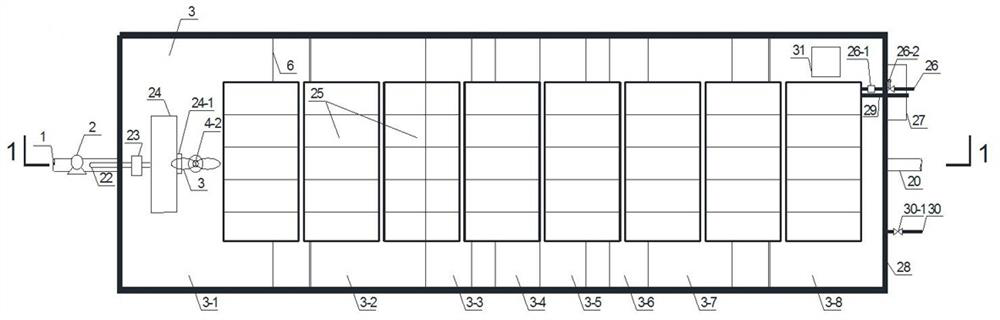
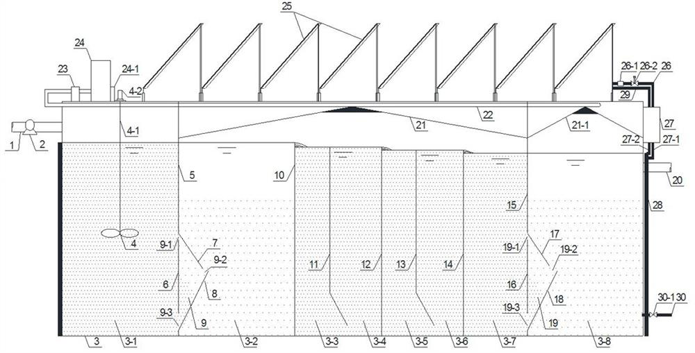
[0021] Such as figure 1 and 2 Shown, a kind of anaerobic baffle reaction device, comprises reaction pool 3, is positioned at in reaction pool 3 and is separated by dividing plate and baffle to form a plurality of hydrolysis fermentation areas and methanogenic area, hydrolysis fermentation area and methanogenic area Connected in series and allow sewage to flow through one by one, the hydrolysis fermentation zone at the front and the methanogenic zone at the rear are connected to the water inlet pipe 1 and the water outlet pipe 20 respectively, and the water inlet pipe 1 is provided with an inlet pump 2 .

[0022] The anaerobic baffle reaction device described in this embodiment also includes a chemical energy power generation system and a solar heating system. The chemical energy power generation system includes a biogas collector 21 (21-1), a biogas collection pipe 22, a biogas preprocessor 23 and a biogas The generator 24, the biogas collector 21 (21-1) is covered above the ...

Embodiment 2

[0036] This embodiment discloses a method for sewage treatment using the solar heat preservation / chemical energy described in Example 1 to drive the anaerobic folded plate flow reaction device, including the following steps:

[0037] 1. Operation of the reaction pool:

[0038] The incoming water (sewage) enters the reaction tank 3 through the water inlet pipe 2 under the suction of the water inlet pump 1. Under the normal working condition of the agitator 4, the pollutants in the sewage flow up and down along the baffle plate in the reaction tank with the water flow. , in the independent hydrolysis fermentation area and methane production area, it is degraded and metabolized by anaerobic activated sludge, so that the water quality is purified. The MLSS of the anaerobic activated sludge in the reaction tank 3 is 8000mg / L-15000mg / L, and the hydraulic retention time is 12-24h. The purified sewage is discharged through the outlet pipe 20 .

[0039] Second, the power of the react...


PUM

PropertyMeasurementUnit
concentrationaaaaaaaaaa

Abstract

The invention discloses an anaerobic baffle plate reaction device and a sewage treatment method, including a reaction pool, a plurality of hydrolysis fermentation areas and methane production areas separated by partition plates and baffle plates in the reaction pool, and a chemical energy power generation system And solar heating system, chemical energy power generation system includes biogas collector, biogas collection pipe, biogas preprocessor and biogas generator, biogas generator is electrically connected with water inlet pump; described solar heating system includes solar heat collector, heat supply Pipes, hot water storage tanks, heat collector supply pipe branches and heat preservation devices. The invention utilizes the heat generated by solar energy to keep the reaction device warm, and the electric energy generated by chemical energy such as biogas powers the reaction device, thereby improving the reaction efficiency of the anaerobic baffle reaction device and solving the problem of high operating cost and energy consumption of the traditional heat preservation device high question.

Description

technical field [0001] The invention relates to an anaerobic baffle reaction device and a sewage treatment method, specifically, an anaerobic baffle reaction device and a sewage treatment method driven by solar heat preservation and chemical energy, which are used for treating sewage. Background technique [0002] Anaerobic baffle reaction tank, as a new type of high-efficiency anaerobic sewage biotechnology, has been widely used. It uses a series of vertically installed baffles in the reaction tank to divide the reaction tank into several reaction chambers in series, and each reaction chamber can be regarded as a relatively independent upflow sludge bed system. Sewage flows up and down along the baffles in the reaction tank, and passes through the sludge bed of each reaction chamber in turn. The high molecular organic substrates in the wastewater, such as cellulose, starch, protein, etc., are hydrolyzed and fermented (acidified) through contact with microorganisms. In the ...

Claims


Application Information

Patent Timeline
Patent Type & Authority Patents(China)
IPC IPC(8): C02F3/28
CPCC02F3/284C02F2201/002Y02E50/30
Inventor 赵茜刘磊张克峰王洪波李梅王金鹤马永山
Owner SHANDONG JIANZHU UNIV
Why Eureka
Try Eureka