Direct injection gas nozzle and engine and power system of direct injection gas nozzle

A technology of gas nozzles and engines, which is applied to gaseous engine fuels, engine components, combustion engines, etc., can solve problems such as ablation, and achieve the effects of small unit volume, light weight, and high energy density

Active Publication Date: 2018-09-18
SHANGHAI KELAIPU ENERGY TECH CO LTD
View PDF12 Cites 2 Cited by
  • Summary
  • Abstract
  • Description
  • Claims
  • Application Information

AI Technical Summary

Problems solved by technology

[0005] The object of the present invention is to provide a direct injection gas nozzle and its engine and power system, which can be used for direct injection of oxygen, hydrogen, natural gas and other fuel gases a

Method used


Image

  • Direct injection gas nozzle and engine and power system of direct injection gas nozzle
  • Direct injection gas nozzle and engine and power system of direct injection gas nozzle
  • Direct injection gas nozzle and engine and power system of direct injection gas nozzle

Examples


Embodiment 1

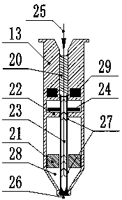
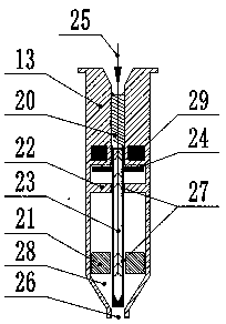
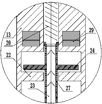
[0041] Gas direct injection nozzle of the present invention such as Figure 1 ~ Figure 4 As shown, the hydrogen gas nozzle 13 is composed of a housing, a gas collection chamber 28, a nozzle orifice 26 and a gas channel 25, and the gas channel passes through the gas collection chamber to communicate with the nozzle orifice. The upper part of the gas passage is equipped with a spring 20, and the lower part is equipped with a hollow plunger 23, and the wall of the hollow plunger tube of the gas collection chamber section of the gas passage is provided with a plunger nozzle 27. The upper part of the gas collection chamber is provided with a gas bearing 22 on the plunger, and the lower part is provided with a gas bearing 21 under the plunger. The device is installed in conjunction with the electromagnetic coil. Through the attraction and release of the plunger stopper by the electromagnetic coil, the hollow plunger moves up and down to realize the opening and closing control of th...

Embodiment 2

[0051] Another embodiment of the present invention is as Figure 7 As shown, the hydrogen fuel engine is a two-stroke engine, including a cylinder 5, a cylinder head 40, a crankcase 35 and a water pan 6, the cylinder head is provided with an oxygen nozzle 34 and a spark plug 36, and the cylinder wall is provided with an air inlet 37 and an exhaust hole 41. A crankshaft 45 is arranged in the crankcase, and a piston 43 is arranged in the cylinder, and the piston is connected with the crankshaft through a connecting rod 44 . The structure of the oxygen nozzle 34 is the same as that of the gas direct injection nozzle in the first embodiment.

[0052] The operation mode of the oxygen direct injection pure hydrogen combustion internal combustion engine power system of the present invention is: 4MPa hydrogen enters the cylinder of the hydrogen fuel engine through the air intake hole, and is ignited by contact with oxygen through piston compression. 2MPa high-pressure oxygen is inje...

Embodiment 3

[0057] The third embodiment of the present invention is as Figure 6 As shown, the hydrogen fuel engine is a four-stroke engine including cylinder 5, water pan 6 and crankcase 35, and the top of the cylinder block is provided with oxygen nozzle 34, spark plug 36, air inlet 38 and exhaust hole 41, and crankcase 35 is provided with Crankshaft 45 is arranged, and in the cylinder body is combustion chamber 46, is provided with piston 43 in the cylinder, and piston is connected with crankshaft 45 by connecting rod 44. The bottom outlet of the water pan 6 of the hydrogen fuel engine is connected to the purification unit, the liquid outlet is connected to the circulating water tank, and the circulating water tank is connected to the water pan 6 through a water supply pipe and a three-way valve. The structure of the oxygen nozzle 34 is the same as that of the gas direct injection nozzle in the first embodiment.

[0058] The operation mode of the oxygen direct injection pure hydrogen ...


PUM


Abstract

The invention relates to a direct injection gas nozzle and an engine and a power system of the direct injection gas nozzle. The nozzle consists of a shell, a gas collecting chamber, a nozzle injectionhole and a gas passage; the gas passage penetrates through the gas collecting chamber and communicates to the nozzle injection hole; the upper part of the gas passage is provided with a spring, and the lower part of the gas passage is provided with a hollow plunger; a plunger injection hole is formed in the pipe wall of the gas collecting chamber section of the gas passage; the upper part of thegas collecting chamber is provided with a plunger upper gas bearing, and the lower part of the gas collecting chamber is provided with a plunger lower gas bearing; the hollow plunger is provided witha plunger limiting stopper; the body of the shell is provided with an electromagnetic coil; and the plunger limiting stopper and the electromagnetic coil are arranged in a manner of matching. The direct injection gas nozzle can be used for direct injection of gases, such as oxygen, hydrogen, natural gas and argon, is capable of resisting high temperature and high pressure, and is not easy to temper; self cooling can be performed on the direct injection gas nozzle by utilizing the injected gas, so that the service life of a hydrogen nozzle is prolonged.

Description

technical field [0001] The invention belongs to the technical field of new energy engines, and relates to a direct injection gas nozzle, an engine and a power system thereof. Background technique [0002] Energy shortage, environmental pollution, and global climate change make it urgent to develop clean, efficient, safe and sustainable energy, among which hydrogen energy is being valued by more and more countries. In the 21st century, the engine industry has developed rapidly, but gasoline engines and diesel engines are still the main types of vehicle engines. Both gasoline and diesel are non-renewable resources. In order to alleviate a series of negative effects brought about by the scarcity of petroleum resources and reduce air pollution and engine exhaust emissions, it is necessary to find alternative fuels for engines, and hydrogen energy is currently the most ideal clean fuel. With the increasingly stringent environmental protection measures around the world, hydrogen ...

Claims


Application Information

Patent Timeline
IPC IPC(8): F02M21/02F02B43/10F02B41/06F02B41/10F02B75/02F01N5/02
CPCF01N5/02F02B41/06F02B41/10F02B43/10F02B75/02F02B2075/025F02B2075/027F02M21/0206F02M21/0227F02M21/0254F02M21/0263Y02T10/12Y02T10/30
Inventor 贾鹏
Owner SHANGHAI KELAIPU ENERGY TECH CO LTD
Why Eureka
Try Eureka