
Performance test system for fuel-driven compressor unit

A compressor unit and testing system technology, applied in the testing of machines/structural components, measuring devices, instruments, etc., can solve problems affecting the accuracy of the performance monitoring system, and achieve accurate and reliable calculations

Inactive Publication Date: 2018-09-28
SHANGHAI JIAO TONG UNIV
View PDF6 Cites 0 Cited by
  • Summary
  • Abstract
  • Description
  • Claims
  • Application Information

AI Technical Summary

Problems solved by technology

However, considering the accuracy of performance calculation, it will affect the overall accuracy of the performance monitoring system

Method used


Image

  • Performance test system for fuel-driven compressor unit
  • Performance test system for fuel-driven compressor unit

Examples


Embodiment 1

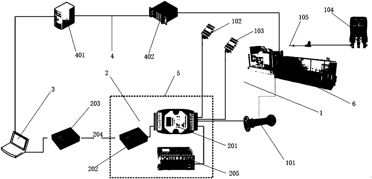
[0028] Such as figure 1 As shown, this embodiment includes a signal acquisition module 1, a signal transmission module 2, and a performance calculation module 3. The signal acquisition module 1 includes a torque meter 101, a temperature sensor 102, a humidity sensor 103, and a flue gas analyzer 104. The flue gas analyzer 104 also has a flue gas probe 105. The signal transmission module 2 includes an analog quantity converter 201, a first optical fiber signal converter 202, a second optical fiber signal converter 203, and an optical fiber 204. The signal acquisition module 1 and the signal transmission module 2 also include a number of necessary power supply devices 205. The analog quantity converter 201, the first optical fiber signal converter 202, and the power supply device 205 are collectively installed in an explosion-proof box 5. The explosion-proof box 5 is arranged near the combustion-driven compressor unit 6. The performance calculation module 3 includes a portable c...

Embodiment 2

[0038] In the field test experiment, first install the acquisition system for several sensor signals of the combustion-driven compressor unit 6 that needs to be tested for performance to collect the signals of the ambient pressure, ambient humidity, flue gas analyzer and torque meter, and then the combustion-driven compressor unit 6 The original measurement point data is input to the test system through other data interfaces, and the software and hardware test system is installed, and the on-site debugging is performed to prepare for the test.

[0039] The main idea of ​​the performance test is to use the speed control strategy of the gas turbine control system. Under the premise of safe operation, select the largest speed range as possible, and in turn make the unit run at the set speed, and start the experiment after the unit is stable.

[0040] Regarding the test speed and range, some parameter requirements are: the lowest running speed of the power turbine: 3965r / min, the normal...


PUM


Abstract

The invention discloses a performance test system for a fuel-driven compressor unit. The performance test system comprises an information collecting module, a signal transmission module and a performance calculating module; the information collecting module comprises several sensors which are the torquemeter, the temperature sensor and the humidity sensor respectively; the signal transmission module comprises a data cable, an analog quantity converter, a first optical fiber signal converter, a second optical fiber signal converter and optical fibers; the performance calculating module comprises a portable computer, a real-time database and modularized modeling software, and all modules of the modularized modeling software apply mechanical vibration parameters of the fuel-driven compressorunit, the torque of driving shafts, the air inlet temperature and the air inlet humidity to calculating the overall efficiency and the overall power of a gas turbine and the efficiency of a compressor. According to the performance test system for the fuel-driven compressor unit, the actual running power and the running efficiency of the compressor unit can be accurately calculated, which brings convenience for a user to accurately estimate the running state of the compressor unit and scientifically formulate a maintenance strategy.

Description

Technical field [0001] The invention relates to the technical field of natural gas transmission pipeline power equipment monitoring, in particular to a performance testing system for a combustion-driven compressor unit. Background technique [0002] PetroChina’s oil and gas pipelines have achieved leapfrog development. A number of large-diameter and long-distance pipelines have been built, including the Shaanxi-Beijing Second Line, the Shaanxi-Beijing Third Line, the Second West-East Gas Pipeline, the Third West-East Gas Pipeline, the Se-Ninglan Line, the Central Asia Line, and the Jining Line. Distance to gas pipeline. As of the end of 2016, China Petroleum Pipeline has installed 312 compressor units, including 186 gas-driven centrifugal units, 75 electric-driven centrifugal units, 51 reciprocating units, and installed approximately 170 units of 30MW gas-driven units, including domestic installations There are 70 GE gas-driven units, 46 SIEMENS gas-driven units, and 54 GE and S...

Claims


Application Information

Patent Timeline
Patent Type & Authority Applications(China)
IPC IPC(8): G01M99/00
CPCG01M99/005
Inventor 周登极梁茂宗张会生马世喜李景轩肖旺沈登海王清亮王辉
Owner SHANGHAI JIAO TONG UNIV
Learn More