
Long-scale uniform thermal plasma arc generating method and device

A thermal plasma generation device technology, applied in the field of plasma physics and applied scientific research, can solve the problems of increasing equipment complexity, melting or gasification, and small arc column area, so as to improve feasibility and flexibility, increase Range and controllability, effects that reduce the difficulty of spawning

Active Publication Date: 2018-09-28
HEFEI INSTITUTES OF PHYSICAL SCIENCE - CHINESE ACAD OF SCI
View PDF10 Cites 3 Cited by
  • Summary
  • Abstract
  • Description
  • Claims
  • Application Information

AI Technical Summary

Problems solved by technology

However, these methods inevitably have some defects: the first method uses a fixed electrode to generate a smaller arc column area, and the available thermal plasma area is reduced; the second and third methods can lengthen the arc column area, increasing the arc column area. An effective thermal plasma area, however, needs to move electrodes or use multi-level electrodes, which will require special design of thermal plasma devices, such as dynamic sealing or multi-level water-cooled electrodes that are sealed and insulated in series for some applications. Increases the complexity of the equipment; the fourth method may introduce impurities, and the conductive liquid may corrode the electrode material and affect the life of the electrode
[0004] At the same time, due to the high current density and energy concentration of arc plasma, the thermal plasma arc or thermal plasma torch with conventional structure has a large temperature gradient
For example, the temperature of the gas at the nozzle of the thermal plasma generation device used for spraying is as high as tens of thousands of degrees, and the particles used for spraying are instantly melted or vaporized, and then the temperature drops sharply during the flight until it hits the substrate and cools down to form a film. Not suitable for applications such as long-scale uniform material preparation or surface treatment

Method used


Image

  • Long-scale uniform thermal plasma arc generating method and device
  • Long-scale uniform thermal plasma arc generating method and device
  • Long-scale uniform thermal plasma arc generating method and device

Examples


Embodiment

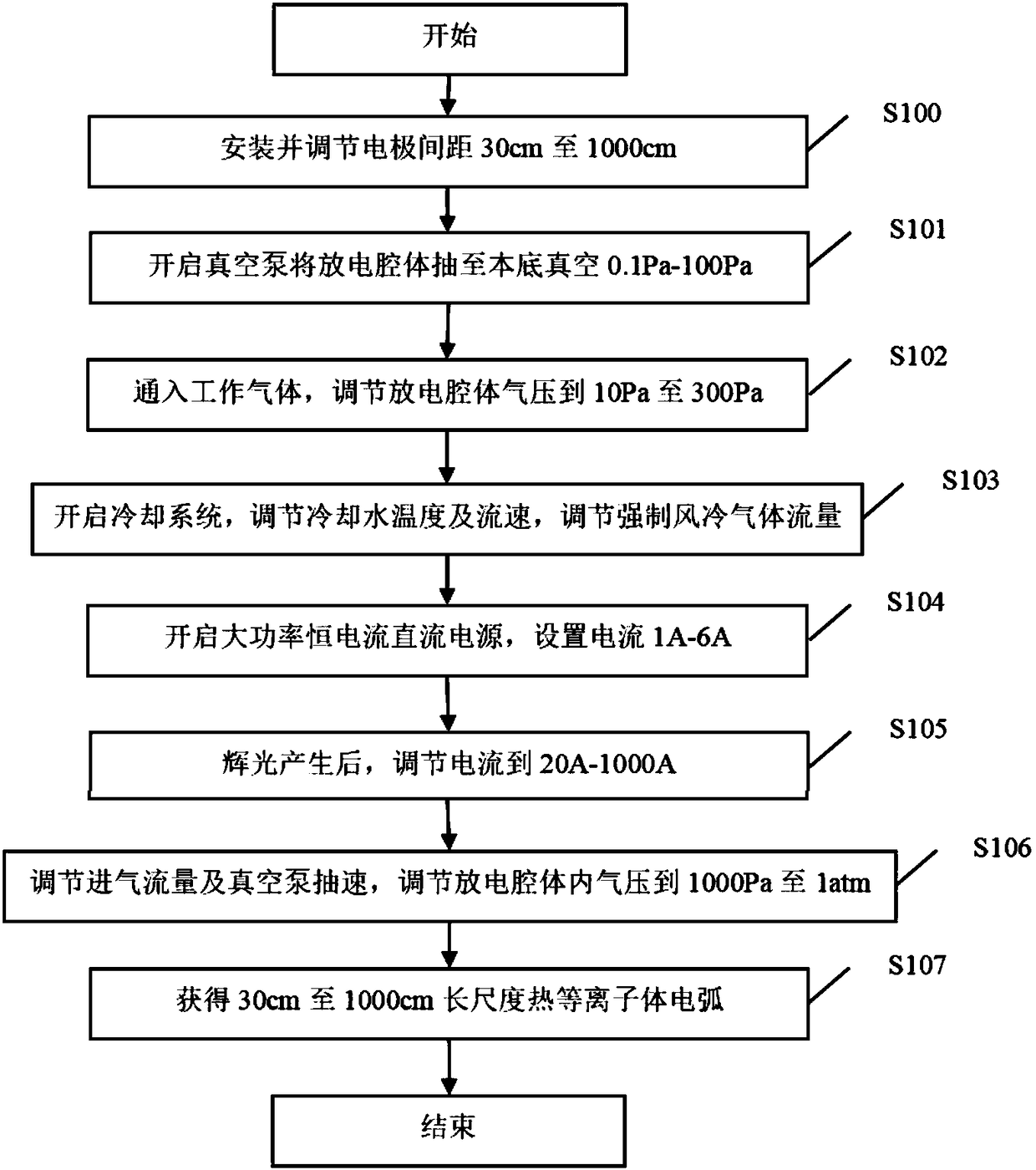
[0036] figure 1 A schematic flow chart of an embodiment of the long-scale uniform thermal plasma arc generation method provided by the present invention, such as figure 1 Shown:

[0037] In step S100, the cathode and the anode, the cathode holder and the anode holder are installed, and the distance between the cathode and the anode is adjusted to be 30 cm to 1000 cm.

[0038] In step S101, the vacuum pump is turned on, and the air pressure in the discharge chamber is evacuated to a background vacuum of 0.1 Pa to 100 Pa.

[0039] In step S102, the working gas is introduced to adjust the pressure in the discharge chamber to 10Pa to 300Pa.

[0040] In step S103, the cooling system is turned on, the cooling water temperature and flow rate are adjusted to effectively cool the cathode, anode, cathode seat, anode seat, and outer wall of the discharge chamber, and the flow rate of forced air-cooled gas is adjusted to cool the outer wall of the plasma generation chamber.

[0041] In...


PUM


Abstract

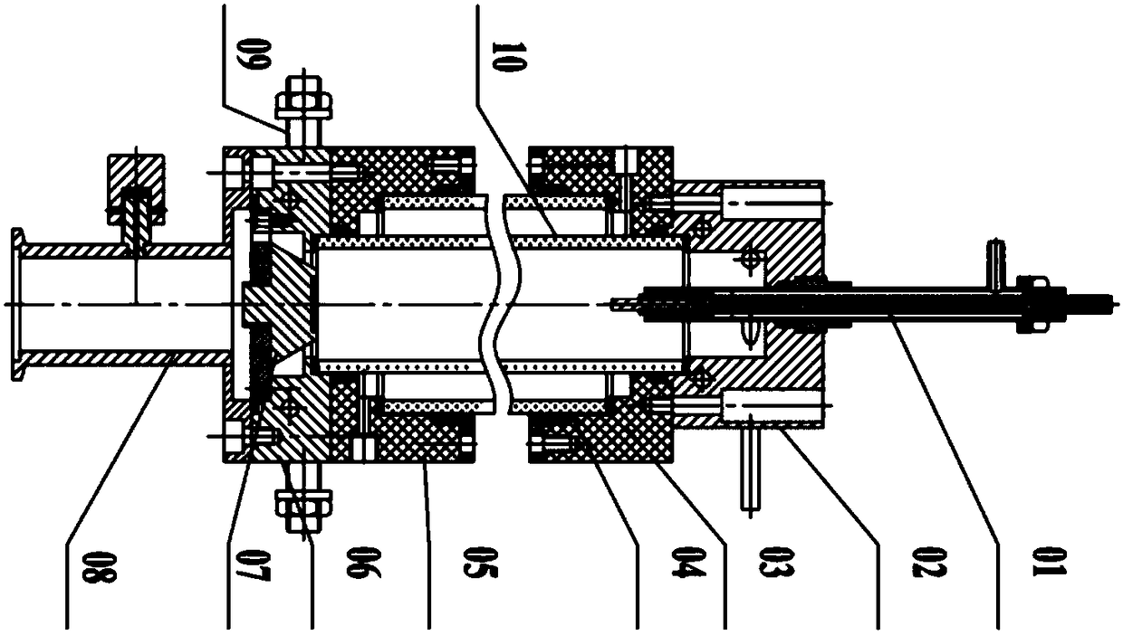
The invention discloses a long-scale uniform thermal plasma arc generating method and device. The device comprises a water cooling cathode, a cathode fixing seat, a cathode end fixing nylon sleeve, anorganic glass tube, an anode end fixing nylon sleeve, an anode fixing seat, a water cooling anode, a vacuuming interface, an anode terminal and a quartz glass tube. The method is advantaged in that plasma atmosphere contamination and electrode corrosion caused by usage of moving electrodes, multi-stage cascade electrodes or introduction of conductive liquids are avoided, difficulty of obtaining long-scale thermal plasma arcs is reduced, moreover, through adjusting the work pressure, a work gas type, the discharge current, an external cooling mode and intensity of a discharge chamber, the cathode and anode spacing, etc., the long-scale uniform thermal stable plasma arcs with controllable plasma length, gas temperature and spatial distribution in the discharge chamber is obtained, and feasibility and flexibility meeting more application environments are improved.

Description

technical field [0001] The invention belongs to the field of plasma physics and applied scientific research, in particular to a method and device for generating long-scale arc thermal plasma. Background technique [0002] Arc plasma belongs to an important classification of low-temperature plasma sources. It is a plasma in a local thermal equilibrium state. It has the characteristics of high current density, high gas temperature (3000K-30000K), energy concentration, low maintenance voltage, and a wide variety of working gases. It is widely used in metal cutting, welding, smelting, spraying, particle spheroidization, dielectric material processing and many other processes that cannot be completed by conventional methods. Generally speaking, DC arc plasma generators can be divided into axial type and coaxial type according to the structure, and different generator structures are selected according to different application objects. For some generators, an external magnetic fie...

Claims


Application Information

Patent Timeline
Patent Type & Authority Applications(China)
IPC IPC(8): H05H1/28H05H1/34
CPCH05H1/28H05H1/34H05H1/3405
Inventor 陈龙威刘甫坤赵颖江贻满孟月东
Owner HEFEI INSTITUTES OF PHYSICAL SCIENCE - CHINESE ACAD OF SCI
Learn More