A kind of deep processing system and processing method of pipe body for automobile

A technology for deep processing and pipe body, which is applied to the deep processing system of automobile pipe body and its processing field, can solve the problems of low cutting efficiency, no separation, easy pressure loss of conveying parts, etc., so as to improve cutting efficiency, improve sustainability, and improve The effect of piping efficiency

Inactive Publication Date: 2020-02-28
CHINA UNIV OF PETROLEUM (EAST CHINA)
View PDF4 Cites 0 Cited by
  • Summary
  • Abstract
  • Description
  • Claims
  • Application Information

AI Technical Summary

Problems solved by technology

This type of cutting method has the following disadvantages: First, the straight pipes to be cut are mostly put on the shelves manually, that is, the single straight pipes to be cut are placed on the workbench in sequence, and after being clamped by the clamping mechanism, they are moved by the clamping mechanism. Drive the cutting straight pipe to be fed to the cutting knife, and a single straight pipe to be cut needs to be cut several times to complete the cutting process, resulting in low cutting efficiency; second, when the cutting knife cuts the straight pipe, the cut straight pipe is Under the action of the high-speed rotation force of the cutting knife, it will fly out of the workbench, which is not only inconvenient for subsequent stacking, but also has certain safety hazards; third, the straight pipes cut by the cutting knife include several straight pipes that meet the specification length And a section of leftover material that does not meet the specification length, the straight pipe and leftover material of the prior art are all blanked to the same place, without separation, which brings new work requirements for subsequent separation; four, the pipe cutting machine of the prior art lacks The stacking mechanism used in conjunction with it, the straight pipes after cutting are mostly stacked by personnel, which is not conducive to the continuity and efficiency of equipment processing
The cooling device for cutting in the prior art, such as an aluminum rod cutting machine with a cooling mechanism disclosed in patent application 201320714314.9, mostly cools the surface of the cutting knife by continuously injecting cooling liquid into the outer surface of the cutting knife; this type of technical solution has the following deficiencies : One, the cooling is mostly concentrated on the outer surface of the cutting knife, the internal heat transfer effect of the cutting knife needs to be improved, and there is a deficiency of low cooling uniformity; second, a large amount of cooling liquid is directly discharged from the bottom of the cutting knife, which is easy on the one hand It corrodes the machine tool and is inconvenient to clean; on the other hand, it will also lead to waste of coolant
This technical solution has the following deficiencies: First, because before each bending work, the straight pipe needs to be manually inserted into the chuck, and the bending process can only be carried out through the clamping and feeding of the chuck. In order to improve the straight pipe feeding The precision to the chuck and the labor consumption of removing manual feeding require an additional configuration of manipulators for straight pipe feeding, and neither manual feeding nor manipulator feeding can properly carry out the feeding and clamping process combination, resulting in poor feeding connectivity; second, when the straight pipe needs to be bent in two directions, the technical solution is to turn the chuck to drive the pipe body to rotate 180° to perform two-way bending; however, for some larger, longer, When the heavy pipe body is rotated, it will inevitably require a large torque, so the fastness of the chuck clamping is also put forward higher requirements; third, because the chuck usually only clamps the end of the straight pipe, The above technical solution is more suitable for bending small straight tubes, especially capillary straight tubes, but when clamping large-sized, heavy-weight tubes, the chuck is prone to overload work
However, this technical solution lacks clamping parts. In the actual bending process, the pipe body is easy to shift, which affects the bending accuracy; in addition, the circular platform rotary bending method is inconvenient to bend a unit pipe body multiple times
[0007] Another example is the all-round continuous pipe bending device disclosed in patent application 201610826960.2. The guide block and the turntable covered by the conveyor belt or chain are used to guide the pipeline, and the movement of the movable wheel is used to change the track of the chain or conveyor belt, so that the guide block presses Turning to the turntable, so that the pipeline can be bent through the cooperation of the knife sunflower and the turntable in the forward conveying state, and then the bending can be realized in different directions; Parts, there are weak contact rigidity and easy pressure damage to the conveying parts, which affects the normal feeding
[0008] In addition, after the pipe body has been stamped, forged, bent, heat treated, etc., there may be differences in its thickness and curvature, resulting in a certain defective rate. For some pipes whose specification deviation is not obvious, usually only in the actual installation discovered when

Method used


Image

  • A kind of deep processing system and processing method of pipe body for automobile
  • A kind of deep processing system and processing method of pipe body for automobile
  • A kind of deep processing system and processing method of pipe body for automobile

Examples


Embodiment 1

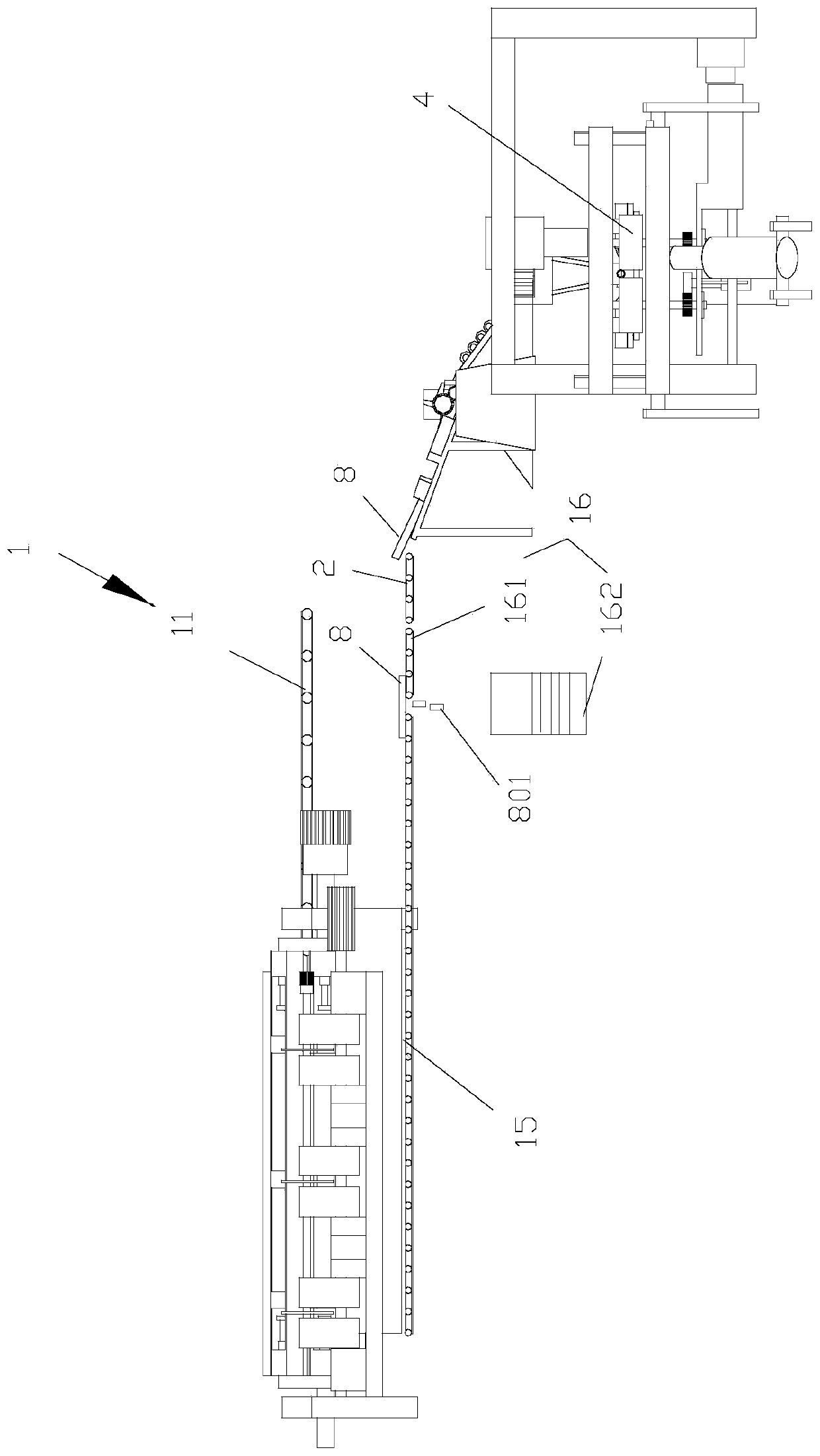
[0048] Such as figure 1 As shown, the present invention discloses an integrated pipe body cutting and stacking mechanism for automobiles, including a cutting mechanism 1, a transfer mechanism 2, a stacking mechanism 3, a pipe bending mechanism 4, a finished product detection mechanism, and a blanking structure. The cutting mechanism 1 is used to cut the straight pipe 7 to be cut, and the transfer mechanism 2 is used to transport the cut straight pipes 8 to the stacking mechanism 3 for stacking. The stacking mechanism is used to feed the straight pipe 8 into the pipe bending mechanism 4, the finished product inspection mechanism is used to detect the pipe body bent by the pipe bending mechanism, and the unloading structure is used to unload the pipe body after inspection .

[0049] Such as figure 1 , 2 As shown, the cutting mechanism 1 includes a first conveying device 11 , an alignment and unloading device 12 , a rotary feeding device 13 , a cutting machine 14 , a second co...

Embodiment 2

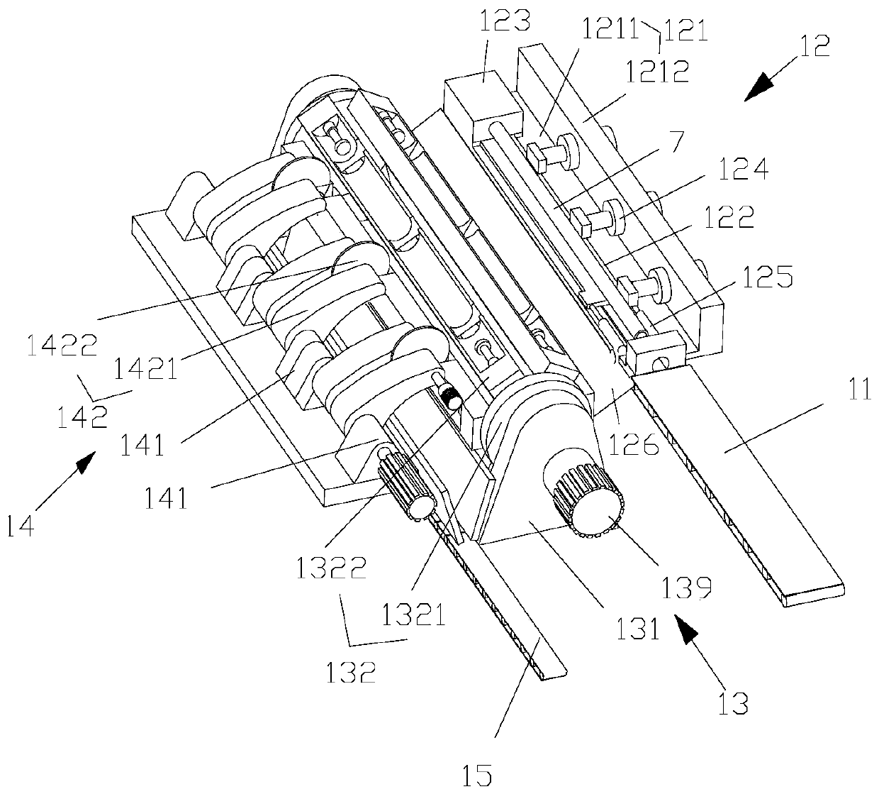
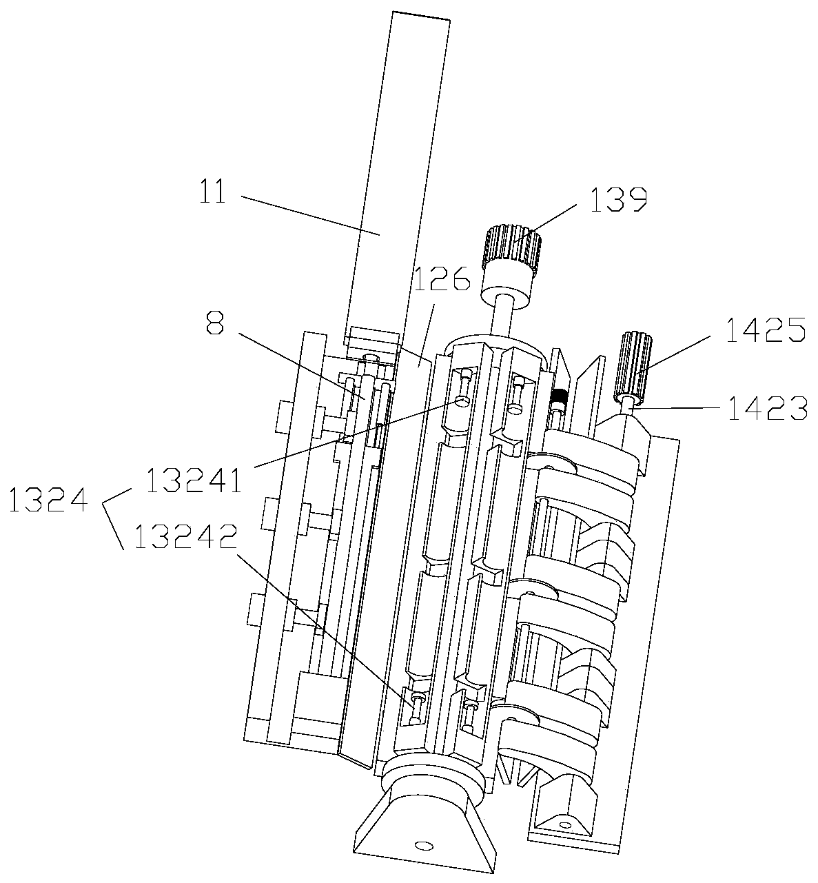
[0061] Such as Figure 2-4 As shown, the difference of this embodiment compared with the above embodiments is that this embodiment provides a cutting machine 14, including a knife seat 141, a swing cutting device, and a plurality of swing cutting devices corresponding to the same feeding The cutouts 13222 on the block 1322 are in one-to-one correspondence. Each oscillating cutting device includes a cantilever 1421 and a cutting knife 1422. The lower end of the cantilever 1421 is rotatably connected to the knife seat 141 by a cutter shaft 1423, and the higher end of the cantilever 1421 is connected to the cutting knife by a knife shaft 1424. 1422 is rotationally connected, the cutter shaft 1423 is driven to rotate by the cutting motor 1425, and the cutter shaft 1424 is driven to rotate by the cutter motor 1426, preferably, between the cutter shaft 1424 and the cantilever 1421, between the knife seat 141 and the cutter shaft 1423 Bearings are set between them. The cutting knif...

Embodiment 3

[0065] The difference between this embodiment and the above embodiment is that: the cutting machine 14 further includes a cooling system, and the cooling system is used to cool the cutting blade 1422 . The cooling system includes a liquid inlet pipe (not shown in the figure), a liquid outlet pipe (not shown in the figure), and the cutter shaft 1424 is a hollow structure, such as Figure 12-14 As shown, a liquid injection channel 14221 is provided inside the cutting knife 1422 , and the liquid injection channel 14221 communicates with the inner cavity of the knife shaft 1424 . Several liquid injection channels 14221 diverge from the center of the cutting knife 1422 to the edge of the cutting knife 1422 in a radial shape. One end of the cutter shaft 1424 is provided with a liquid inlet (not shown in the figure), and the other end of the cutter shaft 1424 is provided with a liquid outlet (not shown in the figure), and a water outlet is provided at the liquid outlet and the liquid...


PUM


Abstract

The invention discloses an automobile pipe body deep machining system. The automobile pipe body deep machining system comprises a cutting mechanism, a transfer mechanism, a stacking mechanism, a pipebending mechanism, a finished product inspection mechanism and a discharging mechanism. The cutting mechanism is used for cutting a straight pipe to be cut. The transfer mechanism is used for conveying the cut straight pipe to the stacking mechanism for stacking. The stacking mechanism is used for feeding the straight pipe into the pipe bending mechanism. The finished product mechanism is used forinspecting the pipe body bent by the pipe bending mechanism. The discharging mechanism is used for discharging the inspected pipe body. The invention further discloses a method for using the automobile pipe body deep machining system to carry out automobile pipe body deep machining. The automobile pipe body deep machining system and the method for using the automobile pipe body deep machining system to carry out automobile pipe body deep machining have the advantages of being higher in cutting efficiency, high in cutting accuracy, convenient for leftover materials separation after cutting iscarried out, high in continuity of stacking, feeding, clamping and bending of straight pipes, and stable in feeding, and having the function of on-line defective product inspection.

Description

technical field [0001] The invention relates to the technical field of auto parts processing, in particular to a deep processing system for an automobile pipe body and a processing method thereof. Background technique [0002] Elbows are widely used in auto parts, such as exhaust pipes, cylinder material pipes, oil pipes, rear suspension beam support pipes, etc. At present, after casting and heat treatment, the billet tubes for automobile processing need to be cut into equal-length tube bodies, and then the tubes are usually processed by a tube bending machine. [0003] Most of the pipe cutting machines in the prior art are linear pipe cutting machines, such as a pipe cutting machine disclosed in patent application 201510966136.2 or a pipe cutting machine disclosed in patent application 201620667104.2. The holding mechanism clamps the main straight pipe to be cut, and then cuts the straight pipe by swinging the cutting knife. This type of cutting method has the following d...

Claims


Application Information

Patent Timeline
Patent Type & Authority Patents(China)
IPC IPC(8): B23P23/06
CPCB23P23/06
Inventor 王龙庭徐兴平汪海王斌王言哲祖国强冯帆刘广斗常汉卿
Owner CHINA UNIV OF PETROLEUM (EAST CHINA)
Why Eureka
Try Eureka