Recycling device for carbon powder

A technology of carbon powder and activated carbon, which is applied in the direction of separating solids from solids with airflow, filtering screens, grids, etc., which can solve the problems of uncontrollable materials, large quantities, continuous operation loss of processes, etc.

Active Publication Date: 2018-10-09
ZHONGYE-CHANGTIAN INT ENG CO LTD
View PDF7 Cites 18 Cited by
  • Summary
  • Abstract
  • Description
  • Claims
  • Application Information

AI Technical Summary

Problems solved by technology

In addition, the round roller feeder often fails during the production process, such as: material leakage when the flue gas pressure changes, and the material cannot be controlled when the machine is stopped.
In addition, the number of round roller feeders is large (as long as one fails, the entire large-scale device has to be shut down), the cost is high, and maintenance is difficult, so it has brought certain restrictions on the development of activated carbon technology.
[0012] Secondly, for the feeding rotary valve in the prior art, there are the following problems: For the transportation of fragile particles such as desulfurization and denitrification activated carbon, the use of rotary valves on the one hand ensures the airtightness of the tower body, and on the other hand realizes the material flow. Transport without damage, but if the conveying medium is sheared due to the rotation of the blades during the conveying process of the rotary valve, see attached Figure 9 , will cause an increase in system operating costs
For a large adsorption tower usually with a height of about 20 meters, the failure of the round roller feeder or the rotary valve during the production process will cause huge losses to the continuous operation of the process, because the adsorption tower is filled with several tons of activated carbon , it is quite difficult to manually dismantle and repair or reinstall, and the impact and loss caused by shutdown are unimaginable

Method used


Image

  • Recycling device for carbon powder
  • Recycling device for carbon powder
  • Recycling device for carbon powder

Examples


Embodiment 1

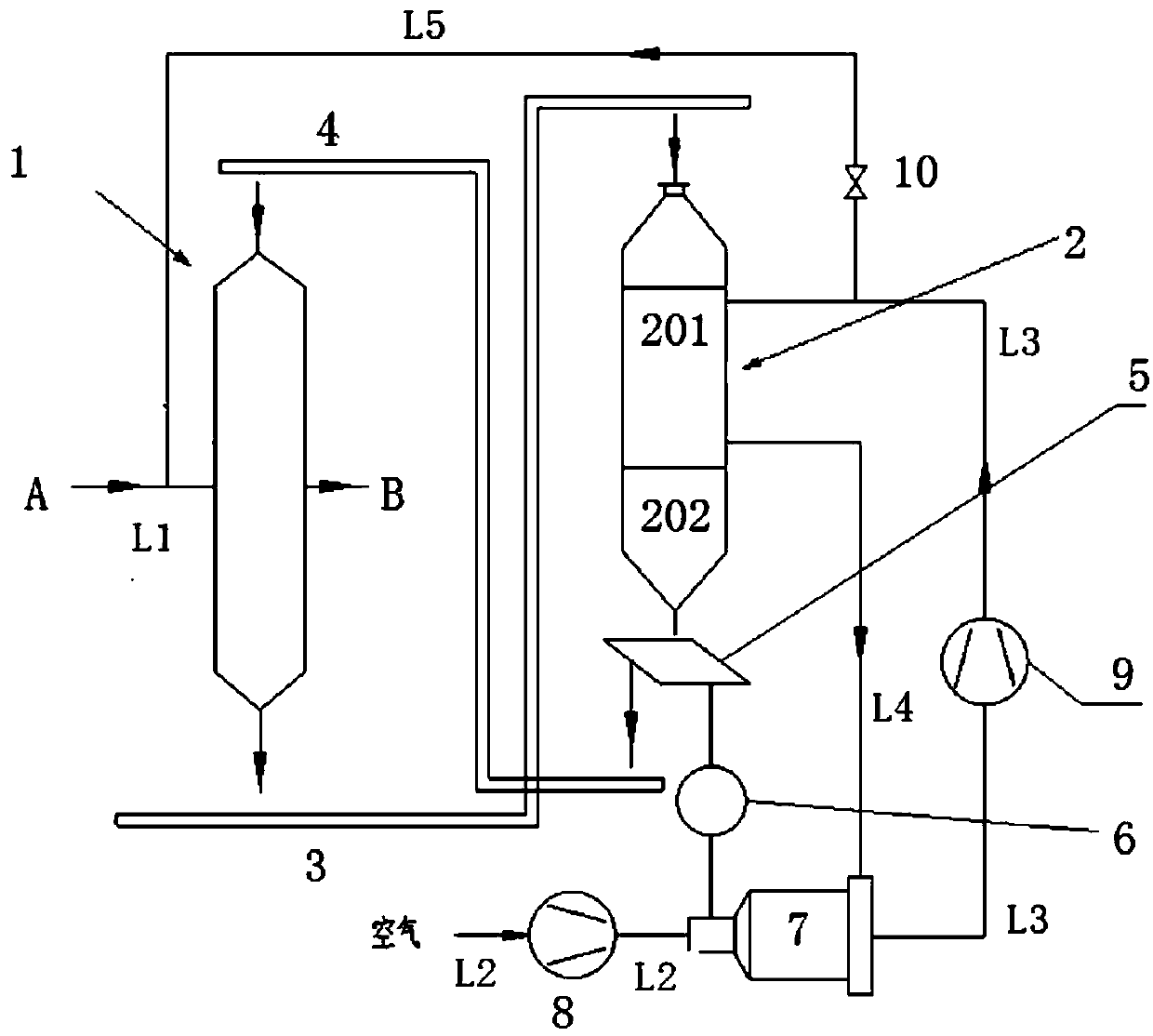
[0086] see figure 2 , provide the recycling device of charcoal powder, the recycling device of this charcoal powder comprises: adsorption tower (1), has the desorption tower (2) of heating section (201) and cooling section (202), the first activated carbon conveyor ( 3), the second active carbon conveyer (4), be positioned at the vibrating screen (5) below the discharge port of desorption tower (2) or downstream, pulverizer (6), heating furnace (7), the blast blower of hot blast stove ( 8), and hot blast circulation fan (9); wherein the hot blast outlet of heating furnace (7) is connected to the hot blast inlet of the heating section (201) of desorption tower (2) via hot blast pipeline (L3), the heating of desorption tower (2) The air outlet of section (201) is connected to the circulating cooling air inlet of heating furnace (7) via circulating cooling air duct (L4); A conveying device is arranged between the machine (6) and the heating furnace (7). Therefore, the fine car...

Embodiment 2

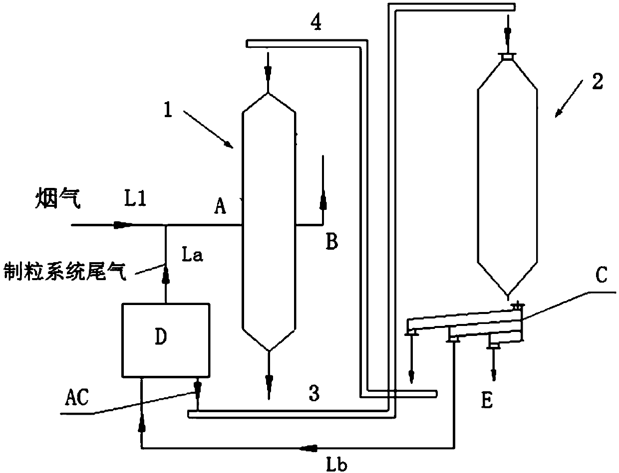
[0092] see image 3 , provides the recycling device of charcoal powder, the recycling device of this charcoal powder comprises: adsorption tower (1), desorption tower (2), the first activated carbon conveyor (3), the second activated carbon conveyor (4), located at The multi-stage or multi-layer vibrating screen (C) below or downstream of the discharge port of the analysis tower (2), and the granulation system (D); wherein the flue gas delivery pipeline (L1) is connected to the flue gas of the adsorption tower (1) The gas inlet (A), the tail gas outlet of the granulation system (D) are connected to the flue gas delivery pipe (L1) via the tail gas discharge pipe (La), and, among them, the multi-stage or multi-layer vibrating screen (C) and the manufacturing A conveying device (Lb) (such as a conveying pipeline) is provided between the granulation system (D) for conveying the fine activated carbon particles screened by the multi-stage or multi-layer vibrating screen (C) to the g...

Embodiment 3

[0099] see Figure 4 , provides the recycling device of charcoal powder, the recycling device of this charcoal powder comprises: adsorption tower (1), desorption tower (2), the first activated carbon conveyor (3), the second activated carbon conveyor (4), located at The multi-stage or multi-layer vibrating screen (C) below or downstream of the discharge port of the analysis tower (2), the sulfur-rich gas acid production system (F), and the waste water purification system (G); wherein the flue gas delivery pipeline (L1 ) is connected to the flue gas inlet (A) of the adsorption tower (1), and the sulfur-rich gas outlet in the middle of the desorption tower (2) is connected to the acid-making system (F) through the sulfur-rich gas pipeline (Lc), and the acid-making system (F) The acid product outlet is connected to the acid liquid inlet of the wastewater purification system (G) through the acid liquid delivery pipeline (Ld), and the tail gas outlet of the acid making system (F) i...


PUM


Abstract

The invention discloses a recycling device for carbon powder. The recycling device for the carbon powder comprises an adsorption tower (1), an analysis tower (2), a first active carbon conveyor (3), asecond active carbon conveyor (4), a vibrating screen (5) or a multi-stage or multi-layer type vibrating screen (C) which is positioned below a discharge hole of the analysis tower (2) or at the downstream of the analysis tower (2), and a heating furnace (7), wherein the analysis tower (2) is provided with a heating section (201) and a cooling section (202); a hot air outlet of the heating furnace (7) is connected with a hot air inlet of the heating section (201) of the analysis tower (2) through a hot air pipeline (L3); an air outlet of the heating section (201) of the analysis tower (2) isconnected to a circulating and cooling air inlet of the heating furnace (7) through a circulating and cooling air pipeline (L4); screened fine carbon powder of the vibrating screen (5) is used as a fuel of the heating furnace (7); and fine active carbon particles screened out by the multi-stage or multi-layer type vibrating screen (C) are conveyed into a pelletizing system (D) for being pelletizedor conveyed into a wastewater purifying system for adsorbing waste acid.

Description

technical field [0001] The invention relates to a device for utilizing fine carbon powder (i.e. recovered carbon powder) produced in an activated carbon method flue gas purification system in the iron and steel field, that is, a desulfurization and denitrification system. The system belongs to an activated carbon method flue gas purification device suitable for air pollution control. The carbon powder utilization device is a carbon powder utilization device combined or integrated in a desulfurization and denitrification system. Background technique [0002] For industrial flue gas, especially sintering machine flue gas in the iron and steel industry, it is ideal to use desulfurization and denitrification devices and processes including activated carbon adsorption towers and desorption towers. In the desulfurization and denitrification devices including activated carbon adsorption tower and desorption tower (or regeneration tower), the activated carbon adsorption tower is use...

Claims


Application Information

Patent Timeline
Patent Type & Authority Applications(China)
IPC IPC(8): B01D53/02B01J20/30B01J20/20C10L5/48C02F1/28B07B1/28B07B9/00
CPCB01D53/02B01D2253/102B01D2259/4009B01J20/20B01J20/3028B07B1/28B07B9/00C02F1/283C10L5/48Y02E50/30
Inventor 魏进超李小龙康建刚
Owner ZHONGYE-CHANGTIAN INT ENG CO LTD
Why Eureka
Try Eureka