Optical-fiber-waveguide automatic alignment coupling instrument based on image processing

An image processing and automatic alignment technology, applied in the coupling of optical waveguides, light guides, optics, etc., can solve the problems of slow alignment speed, complex chip manufacturing process, high coupling loss, and avoid long-term operation.

Active Publication Date: 2018-10-12
BEIHANG UNIV
View PDF7 Cites 11 Cited by
  • Summary
  • Abstract
  • Description
  • Claims
  • Application Information

AI Technical Summary

Problems solved by technology

This method has high precision, but generally manual alignment is used in the initial light-passing stage, and the alignment speed is slow; currently, algorithms for fine alignment with feedback adjustment include hill climbing method, polynomial fitting method, simplex method, Hamilton algorithm, and centroid method , genetic method, etc., can effectively search for the maximum coupling position, but they are all limited by the low real-time feedback of the optical power meter and the large data volatility, each has its own advantages and disadvantages
[0006] The passive passive alignment method uses semicon

Method used


Image

  • Optical-fiber-waveguide automatic alignment coupling instrument based on image processing
  • Optical-fiber-waveguide automatic alignment coupling instrument based on image processing
  • Optical-fiber-waveguide automatic alignment coupling instrument based on image processing

Examples


Embodiment Construction

[0076] The present invention will be further described in detail below in conjunction with the accompanying drawings.

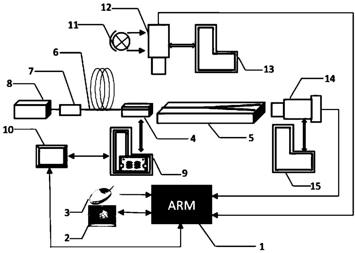
[0077] A fiber-waveguide automatic alignment coupling instrument based on image processing of the present invention, such as figure 1 As shown, it includes image acquisition module, image processing and control module, motion execution module and human-computer interaction module.

[0078] The image acquisition unit includes a white light source 11, a laser 8, an optical fiber adapter 7, and two sets of microscope-CMOS cameras.

[0079] The laser 8 directly couples the red light into the pigtailed liner 4 through the bare fiber adapter 7; the pigtailed liner 4 is opposite to the Y waveguide element 5 for coupling; two groups of CMOS cameras are connected with the microscope objective lens, the first A group microscope-CMOS camera 12 is vertically fixed above the pad-waveguide coupling point to perform microscopic imaging on the coupling point. The white lig...


PUM


Abstract

The invention discloses an optical-fiber-waveguide automatic alignment coupling instrument based on image processing, and belongs to the technical fields of optical fiber communication and optical fiber sensing. The optical-fiber-waveguide automatic alignment coupling instrument based on image processing includes an image acquisition module, an image processing and control module, a motion execution module and a man-machine interaction module, wherein the motion execution module includes a pigtail filler block, a Y waveguide element, a six-dimensional electric displacement table, a motor control panel, two sets of hand-operated displacement tables and the like, wherein the image processing and control module includes a processor, a storage module, a communication interface and a display module; and the image acquisition module acquires side surface images and end surface images with clear definition, and then the motion execution module extracts the edge feature straight lines from theside surface images with clear definition and calculates the relative deviation after the side surface images and end surface images are processed by the image processing and control module, then eliminates the deviation to realize initial light, determines the output point position and controls the maximum gray value of the output light point to achieve automatic alignment coupling of the fiber-Y waveguide. The optical-fiber-waveguide automatic alignment coupling instrument based on image processing has the advantages of small volume, low cost, friendly man-machine interaction and high operation speed, and can avoid long time operation of artificial alignment.

Description

technical field [0001] The invention belongs to the technical field of optical fiber communication and optical fiber sensing, and relates to an optical fiber-waveguide automatic alignment coupling instrument based on image processing. Background technique [0002] In the 21st century, the development and use of optoelectronic devices has become a strategic technology for the development of various countries in the fields of communication and sensing. In terms of optical fiber communication, integrated optoelectronic devices have become the key devices supporting the rapid development of next-generation optical fiber communication due to their stable performance, high degree of integration, fast processing speed and high reliability. Waveguide devices are important basic components of integrated optoelectronic devices, and the low-loss connection and packaging technology of optical fibers and waveguides is the key technology of integrated optoelectronics technology. [0003]...

Claims


Application Information

Patent Timeline
IPC IPC(8): G02B6/38
CPCG02B6/385
Inventor 宋凝芳李亮冯迪张春熹
Owner BEIHANG UNIV
Why Eureka
Try Eureka