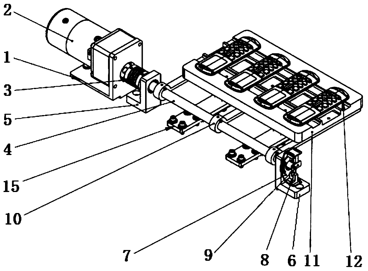
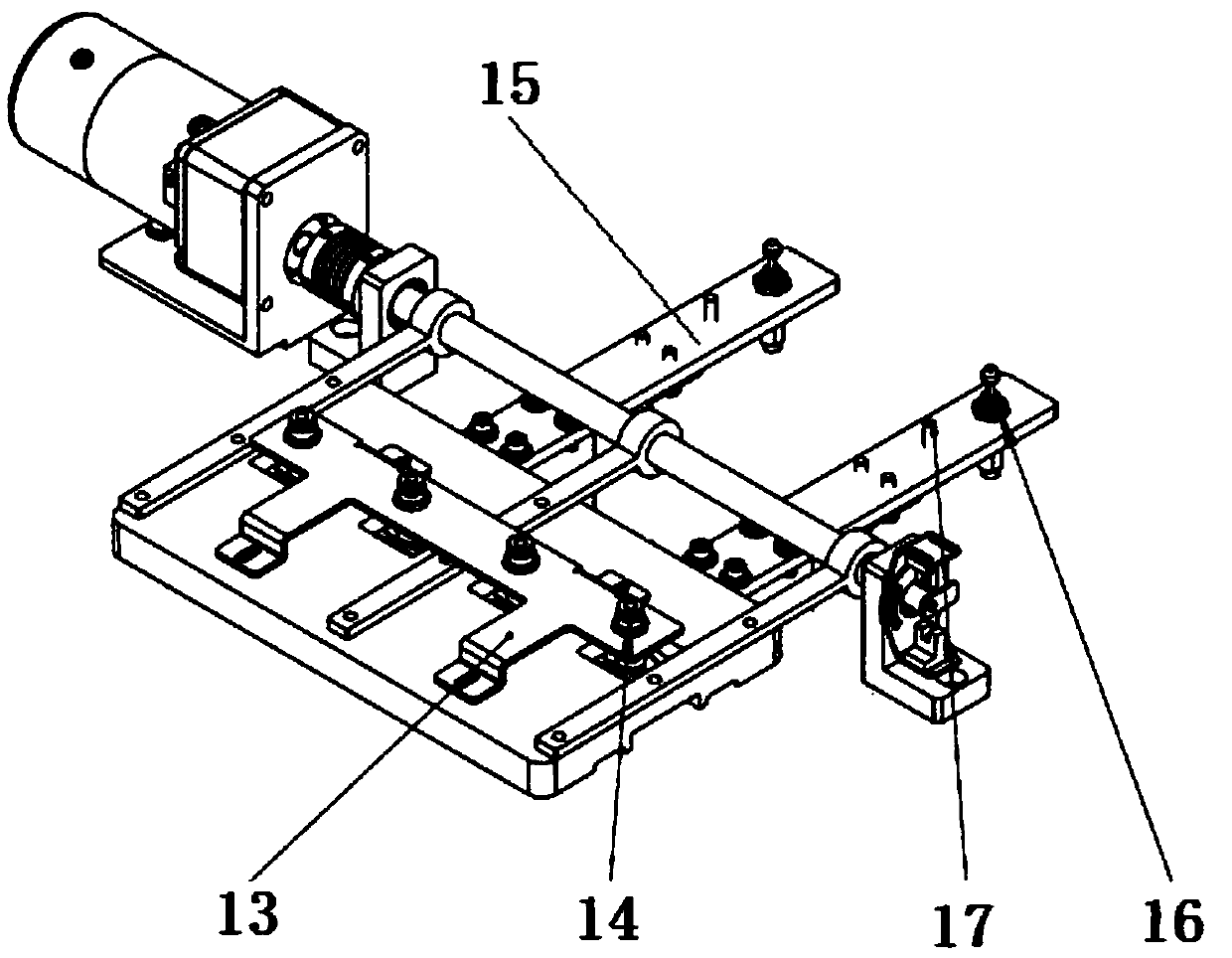
Modern remote controls are mainly composed of
integrated circuit boards, housings and devices used to generate different messages (the definition of messages in communication science: composed of a group of interrelated meaningful symbols that can express a complete meaning of information) It is composed of buttons; at present, the connection between the production,
assembly and testing process of the remote control is done manually. After the
assembly process is completed, the remote control is packed or transferred to the test
machine station with an
assembly line, and then manually placed in the test
machine. Tested in the test
machine, such a production mode is relatively inefficient and poor in consistency; automatic loading is mostly held by a six-axis
robot or sucked and placed on a remote control, such a production mode, the cost is relatively high; there are many automatic Feeding mechanism:
Chinese patent 201621392587.6 discloses a power
lithium battery conductive strip installation tooling including a tooling plate. The tooling plate has mounting holes that can accommodate the conductive strips. The shape and size of the mounting holes correspond to the shape and size of the conductive strips. There is a fixed seat for positioning the conductive strip in the installation hole. The position of the fixed seat corresponds to the conductive
electrode column of the
battery cell of the power
lithium battery. The fixed seat includes a seat body, and at least a pair of clips are arranged in the seat. The gap is greater than the thickness of the conductive strip. The end of the conductive strip extends between the clips, and the clip restricts the conductive strip. There is a tightening knob on the seat body. To clamp or loosen the clips, a compression spring is provided between the clips, and the clips are pushed to both sides by the compression springs; the feeding and turning mechanism of the single-phase electric watch case
light guide column
assembly machine disclosed in
Chinese patent 201720329981.3 includes a bottom plate. A riser is installed on the bottom plate, a vertical rotation mechanism is installed on the riser, a horizontal rotation feeding mechanism is installed on the top of the vertical rotation mechanism, and the vertical rotation mechanism includes a turntable and a support plate. The first rotating motor is arranged on the vertical plate, the rotating shaft of the first rotating motor is connected to the center of the turntable, the support plate is horizontally connected to the top edge of the turntable, and the horizontal rotating feeding mechanism includes The second rotating motor, the second rotating motor is installed on the support plate, and the rotating shaft of the second rotating motor is connected with a material receiving frame, and the material receiving frame is provided with left and right symmetrical material receiving trays;
Chinese patent 201720224488.5 discloses A turning assembly of a
brake pump pump cover loading machine, the turning assembly of the brake pump pump cover loading machine includes a material shifting installation plate, and the material moving installation plate is provided with a turning slot and two avoidance slots. The upper end surface of the mounting plate is fixed with a first flipping mounting plate and a second flipping mounting plate perpendicular to it, the first flipping mounting plate and the second flipping mounting plate are respectively located on both sides of the flipping slot on the shifting mounting plate, the first turning Both the overturning mounting plate and the second overturning mounting plate are provided with round holes, and the opposite inner surfaces of the first overturning mounting plate and the second overturning mounting plate are respectively provided with a first overturning slideway and a second overturning slideway, and the first overturning slideway The structure of the track and the second overturning slideway is the same; a kind of overturning automatic feeding device disclosed in Chinese patent 201710726255. Extending horizontally, the push rod It is the output shaft of the
linear drive device. The front end of the push rod is fixedly connected to the end of the rack. The upper surface of the rack is a
tooth surface, and the lower surface is no
tooth surface. The gear is located above the rack and meshes with the
tooth surface of the rack. The limit wheel Located below the meshing part of the rack and the gear, the toothless surface of the rack is caught in the limit groove on the circumferential surface of the limit wheel, the gear is fixed on one end of the rotating shaft, and the rotating shaft extends horizontally and is perpendicular to the surface of the gear. The material
barrel is fixed on the other end of the rotating shaft through the material
barrel bracket, and the top of the material
barrel has a
discharge port; Chinese patent 201720209621. The turning unit of the machine includes a transposition mounting plate, the upper plane of the transposition mounting plate is fixed with a ring rack mounting seat, and a round hole is arranged on the ring rack mounting seat, and the upper plane of the ring rack mounting seat is fixed on the periphery of the circular hole. There is a ring rack, and the lower plane of the transposition mounting plate is fixed with a motor mounting base, and the lower plane of the motor mounting base is fixed with a motor. After passing through the transposition mounting plate, the rotating plate is fixed through the oil sleeve, and the rotating plate is located in the round hole of the ring rack mounting seat; a feeding mechanism that can stably feed and has the function of turning over is disclosed in Chinese patent 201710224452.1, including the bottom plate , two first fixed blocks and two second fixed blocks are fixedly connected to both sides of the upper surface of the bottom plate respectively, and the two first fixed blocks and the two second fixed blocks are respectively located at the front and rear ends of the two sides of the bottom plate , the opposite sides of the two first fixed blocks and the two second fixed blocks are respectively connected by a first rotating rod and a second rotating rod, and rollers are sleeved on the first rotating rod and the second rotating rod , and the two rollers are connected by a
conveyor belt drive; a
solar cell flipping and feeding device disclosed in Chinese patent 201621492537.5 includes a flipping assembly and two sets of conveying assemblies, the flipping assembly is located between the two sets of conveying assemblies, and each set of conveying assemblies includes a
conveyor belt , the turning assembly includes a middle part and two sets of turning parts, the two sets of turning parts are fixed on the middle part, and are symmetrical to the center of the middle part, the middle part is a frame with a through hole, and the lower bottom surface of the through hole is flush with the
conveyor belt , the turning part includes two groups of brackets, on which there are several suction cups, and the middle part is driven by a motor to rotate; Chinese patent 201621259082.2 discloses a return spring turning device for a return spring automatic feeding machine, the return spring is automatically loaded The return spring turning device of the machine includes two symmetrically fixed return spring turning assemblies with the same structure. The vertical linear guide rail mounting plate is fixed vertically through the reinforcing ribs. There is a rectangular opening on the vertical linear guide rail mounting plate. Two parallel vertical Linear guide rails, a first
telescopic cylinder connecting plate is fixed on the sliders of the two vertical linear guide rails at the same time; the battery flipping and feeding mechanism disclosed in Chinese patent 201621164752.2 includes A fixed plate, the surface of the fixed plate is slidingly installed with a slider connecting plate, and the fixed plate is fixed with a lifting power mechanism for driving the slider connecting plate to move up and down relative to the fixed plate. A rotary power mechanism is fixed, the output end of the rotary power mechanism is connected to the rotary mechanism, and the rotary mechanism includes a rotary mounting plate and two suction units, and the two suction units are respectively installed on the upper surface of the rotary mounting plate and the On the lower surface, the rotating power mechanism can realize the index rotation of two suction units by 180°; Chinese patent 201710224317.7 discloses a
capacitor fixative flip feeding
system including machine base, guide shaft, fixative storage flip assembly, step type Guide shaft, chain lifting component, overturn limit component, limit collar, top plate, machine base for fixing guide shaft, stepped guide shaft and chain lifting component, fixative storage flip component for storing fixative, by chain The lifting component drives it to move up and down, and realizes flipping and blanking under the action of the turning limit component. The limit collar is used to limit the turning limit component. The top plate is used to install the upper bearing seat mounting plate. The bit collar is connected and locked with the guide shaft and the stepped guide shaft through nuts; the above patented products cannot be applied to the remote control automatic flip feeding process, and the low efficiency of manual flip feeding cannot be avoided

