Core-shell structure nanometer composite particle as well as preparation method and preparation device thereof

A core-shell structure and nanocomposite technology, applied in nanocarbon, nanotechnology, nanotechnology and other directions, can solve the problems of low preparation temperature, inability to prepare materials, particle aggregation, etc., to achieve simple process operation, simple process flow, continuous production. Effect

Active Publication Date: 2018-10-19
TSINGHUA UNIV
View PDF10 Cites 12 Cited by
  • Summary
  • Abstract
  • Description
  • Claims
  • Application Information

AI Technical Summary

Problems solved by technology

However, the liquid-phase method has the following disadvantages: (1) The preparation temperature is low, and many materials that require high-temperature synthesis cannot be prepared, and the selection of material systems is limited; (2) The force between the core structure and the shell structure is weak, and it is easy to occur The separation of the core structure and the shell structure; (3) the phenomenon of particle aggregation is very easy to occur, and it is difficult to obtain the core-shell structure nanocomposite particles with good dispersion; (4) the deposition and surface reaction method and the sol-gel method are two step method, it is easy to cause side reactions on the surface of the core structure before coating the shell structure, such as surface oxidation, so that the expected core-shell structure particles cannot be obtained
[0005] Compared with the liquid-phase method, the preparation of core-shell nanocomposite particles by the gas-phase method has simple steps, good particle dispersion, and is conducive to industrial production; but there are also problems such as uneven coating of the shell structure and wide particle size distribution.

Method used


Image

  • Core-shell structure nanometer composite particle as well as preparation method and preparation device thereof
  • Core-shell structure nanometer composite particle as well as preparation method and preparation device thereof
  • Core-shell structure nanometer composite particle as well as preparation method and preparation device thereof

Examples


Embodiment 1

[0043] Example 1 Preparation of composite particles from precursors from different sources

[0044] Proceed as follows:

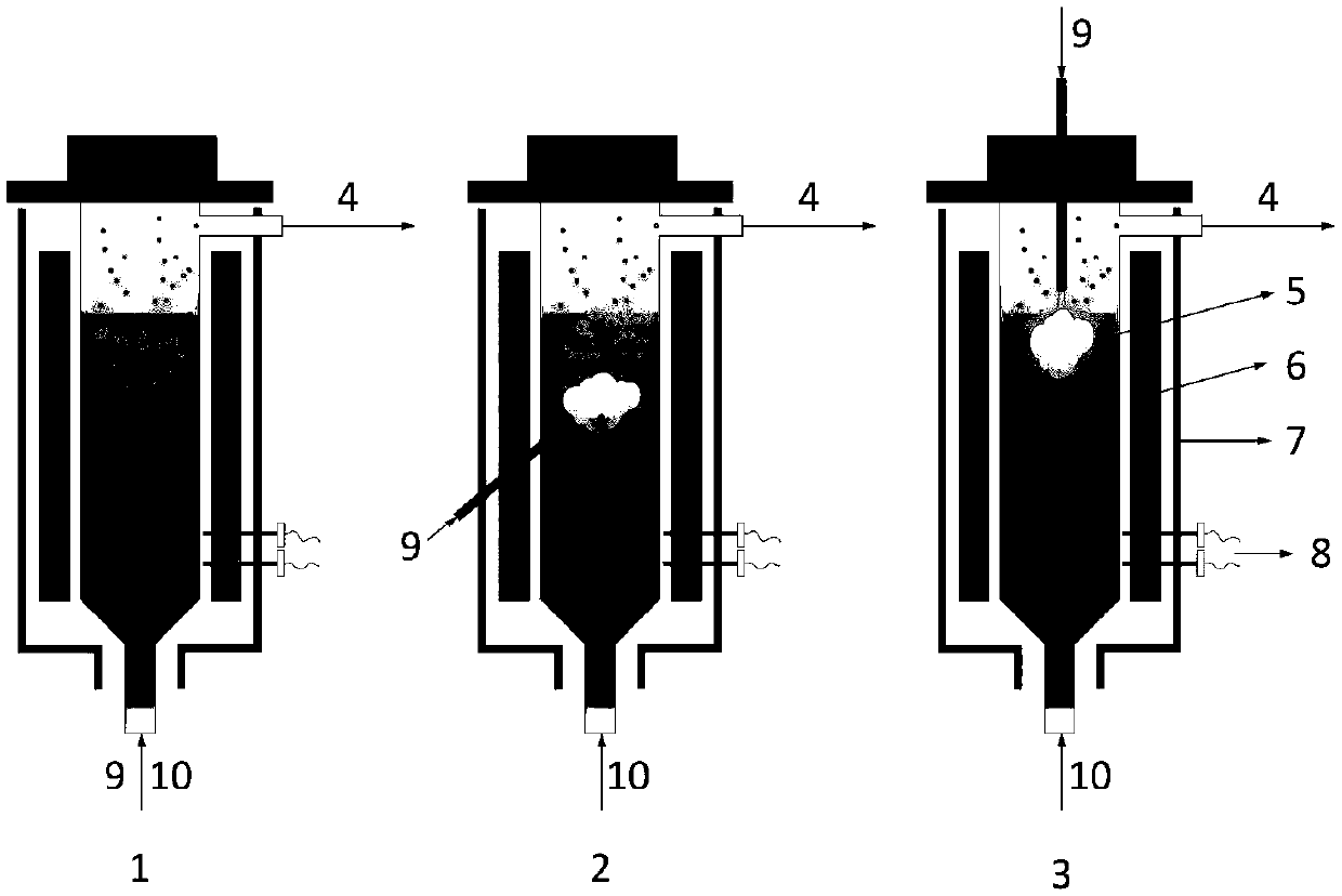
[0045] (1) Hexamethyldisilane, the precursor of the core material, was heated to 80°C by heating in a water bath, hydrogen was used as the carrier gas, and the flow rate of the carrier gas was 0.6L / min;

[0046] (2) After mixing the shell material precursor propylene and the core material precursor, pass it into the fluidized bed reactor from the bottom, and the flow rate of propylene is 2.0L / min;

[0047] (3) The mixed gas of hydrogen and argon is used as the fluidization gas, the flow rate of hydrogen is 1.2L / min, and the flow rate of argon is 1.5L / min;

[0048] The fluidized bed reactor is heated to 1000°C to start the reaction, and the powder is collected through the powder collection system at the top of the reactor.

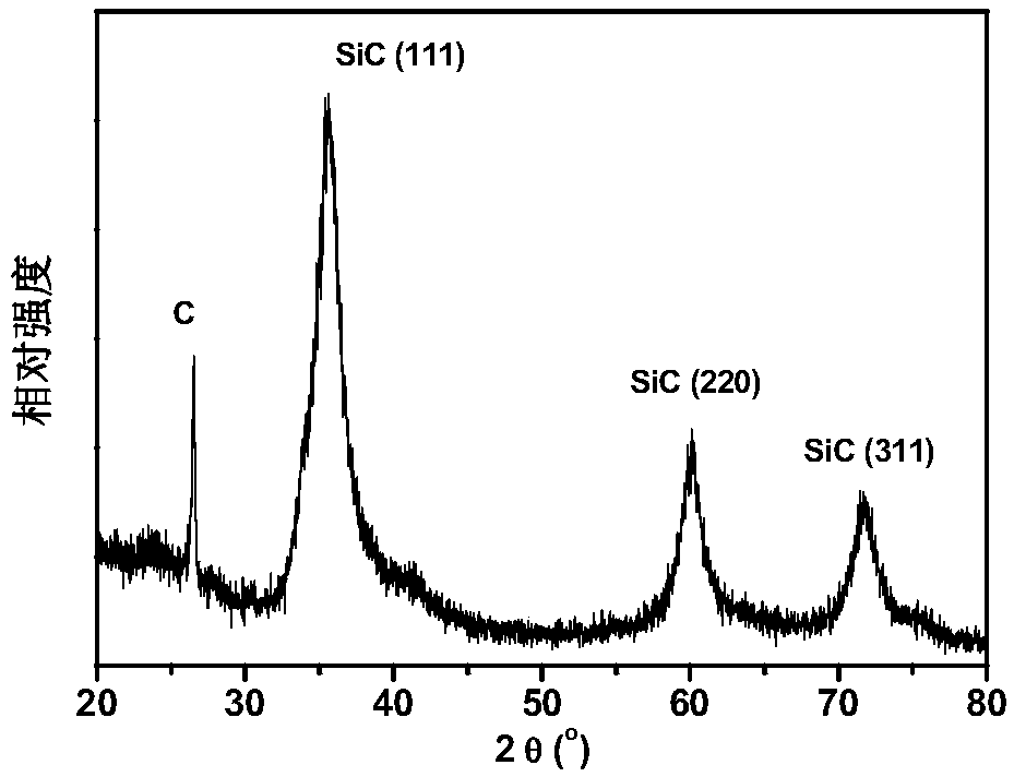
[0049] The obtained powder product is a core-shell structure particle with silicon carbide as the core structure and elemental carbon...

Embodiment 2

[0050] Example 2 Preparation of composite particles from precursors from different sources

[0051] Proceed as follows:

[0052] (1) Hexamethyldisilane, the precursor of the core material, is heated to 80°C by heating in a water bath, hydrogen is used as the carrier gas, and the flow rate of the carrier gas is 0.6L / min, and it enters the fluidized bed reactor from the bottom ;

[0053] (2) Heat the aluminum sec-butoxide precursor of the shell material to 150°C by electric heating, use argon as the carrier gas, and the flow rate of the carrier gas is 1.5L / min, and enter the fluidized bed reactor from the top;

[0054] (3) The mixed gas of hydrogen and argon is used as the fluidization gas, the flow rate of hydrogen is 1.2L / min, and the flow rate of argon is 1.5L / min;

[0055] Heat the fluidized bed reactor to 1100°C to start the reaction, and collect the powder through the powder collection system at the top of the reactor;

[0056] (4) The obtained powder was heat-treated a...

Embodiment 3

[0058] Example 3 Preparation of Composite Particles from Different Sources of Precursors

[0059] Proceed as follows:

[0060] (1) Heat the core material precursor aluminum sec-butoxide to 150°C by electric heating, use argon as the carrier gas, the flow rate of the carrier gas is 1.0L / min, and enter the fluidized bed reactor from the bottom;

[0061] (2) Heat copper acetylacetonate, the precursor of the shell material, to 160°C by electric heating, use argon as the carrier gas, and the flow rate of the carrier gas is 0.3L / min, and enter the fluidized bed reactor from the side wall;

[0062] (3) The mixed gas of hydrogen and argon is used as the fluidization gas, the flow rate of hydrogen is 0.8L / min, and the flow rate of argon is 1.5L / min;

[0063] Heat the fluidized bed reactor to 900°C to start the reaction, and collect the powder through the powder collection system at the top of the reactor;

[0064] (4) The obtained powder was heat-treated at 800° C. for 1 hour under a...


PUM

PropertyMeasurementUnit
sizeaaaaaaaaaa
sizeaaaaaaaaaa

Abstract

The invention relates to a core-shell structure nanometer composite particle as well as a preparation method and a preparation device thereof. The preparation method comprises the following steps of using a fluidized bed chemical vapor deposition method; respectively obtaining core materials and shell materials in a way of controlling the temperature region distribution in a fluidized bed reactorand a precursor steam inlet; realizing in-situ coating; obtaining the core-shell structure nanometer composite particle. The prepared core-shell structure nanometer composite particle has the advantages that the coating between the core and the shell is uniform; the particle shape and dimension are controllable; various function coupling of the material can be realized; the core-shell structure nanometer composite particle is applied to the fields of biological medicine, electronic and semi-conductors, luminescence, catalysis and the like. The technical flow process is simple; the operation ofthe process is convenient and fast; the cost is low; the industrial production can be favorably realized.

Description

technical field [0001] The invention relates to the technical field of preparation of core-shell structure nano-composite particles, in particular to a core-shell structure nano-composite particle, its in-situ fluidized bed chemical vapor deposition preparation method, and a preparation device thereof. Background technique [0002] Core-shell structure nanocomposite particles are two-phase composite materials composed of core structure materials and shell structure materials, which not only have the independent properties of core particles and shell materials, but also obtain unique coupling properties from the combination of core and shell materials. Performance has been widely concerned and researched. [0003] Core-shell structure nanocomposite particles can be divided into inorganic / inorganic, inorganic / organic, organic / inorganic and organic / organic core-shell structure particles according to the composition of core and shell two-phase materials. Due to the diversity an...

Claims


Application Information

Patent Timeline
Patent Type & Authority Applications(China)
IPC IPC(8): C01B32/977C01B32/15C01F7/30B82Y30/00B82Y40/00C23C16/442C23C16/40C23C16/32C23C16/26C23C16/18B22F1/00
CPCC23C16/18C23C16/26C23C16/325C23C16/403C23C16/442B82Y30/00B82Y40/00C01B32/15C01B32/977C01F7/30C01P2004/64C01P2004/80C01P2002/72C01P2004/04B22F1/0553B22F1/054
Inventor 刘荣正赵健刘马林常家兴邵友林刘兵
Owner TSINGHUA UNIV
Why Eureka
Try Eureka