Diffusion pump

A diffusion pump and pump core technology, applied in the field of diffusion pumps, can solve the problems of easy oxidation and burnout of resistance wires, passive combination, and high heat loss.

Inactive Publication Date: 2018-10-23
戴海玥
View PDF0 Cites 1 Cited by
  • Summary
  • Abstract
  • Description
  • Claims
  • Application Information

AI Technical Summary

Problems solved by technology

The evaporation system is one of the most important components of the diffusion pump. The existing evaporation system uses resistance heating (resistance wire, etc.) or electromagnetic induction heating to heat all the pump oil and the bottom of the diffusion pump. The disadvantages are The pump oil and the pump body of the diffusion pump have large heating capacity, slow heating speed, uneven heating, long start-up time of the diffusion pump, large heat loss, high power of the heating furnace, high energy consumption, and low efficiency. It is prone to bumping, easy to decompose and deteriorate, the evaporation system and the cooling system cannot be completely separated (connected through the pump body), the internal friction is large, the resistance wire is easy to oxidize and burn, and the replacement of the resistance wire requires a long downtime. After the diffusion pump stops working, the pump The oil is in a high temperature state for a long time, which is easy to oxidize and deteriorate, which reduces the service life of the pump oil. The cooling speed of the evaporation system is slow, and the cooling system needs to prolong the working time, which increases the operating cost. In addition, because the diffusion pump is working, the pump oil The quantity is decreasing and the composition is constantly changing, resulting in constant changes in the working conditions of the diffusion pump, making the vacuum degree prone to fluctuations and oil return phenomenon; the start-up time of the existing diffusion pump is relatively long, which takes about 20-80 minutes , the reason for its slow start is that the heating capacity is large, the heating rate of the pump oil is slow, and the pump core needs pump oil to heat; the nozzle of the existing diffusion pump is a fixed umbrella-shaped diffusion nozzle, and the steam forms a stable flow after being ejected from the nozzle. The umbrella-shaped airflow relies on diffusion motion to make the extracted air molecules enter the steam flow. Its disadvantages are that the contact surface between the steam and the air is small, the combination is passive, the extraction force is small, the vacuuming efficiency is low, the ultimate vacuum is low and the return rate is low. high oil rate

Method used


Image

  • Diffusion pump
  • Diffusion pump
  • Diffusion pump

Examples


Embodiment 1

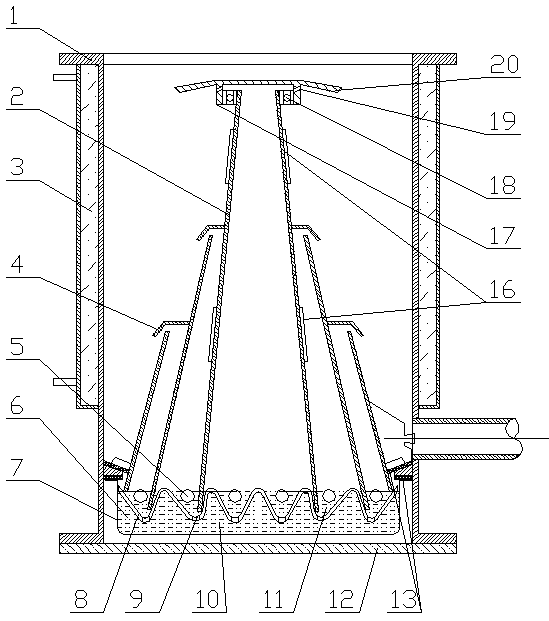
[0032] Embodiment 1: the embodiment of a kind of diffusion pump of the present invention is as figure 1As shown, the basic structure includes: pump body 1, pump core 2, cooling system 3, injection system 4, pump oil 6, evaporation system 7 and control system, pump core 2 is equipped with a heating device 16, and injection system 4 adopts a rotary Spray head, rotary spray head 17 is installed on the upper end of steam conduit through bearing 18, can install one or several, blade 20 can also be installed on the rotary spray head 17, to further improve the performance of diffusion pump; Cooling system 3, pump oil 6 and control system Basically the same as the prior art, the pump body 1 can be divided into straight cavity and convex cavity. For the convenience of assembly, the bottom of the pump body 1 can be provided with a movable bottom plate 12; Heat insulation is installed inside the pump body 1. The outer surface of the evaporation system 7, the inner surface of the pump bod...

Embodiment 2

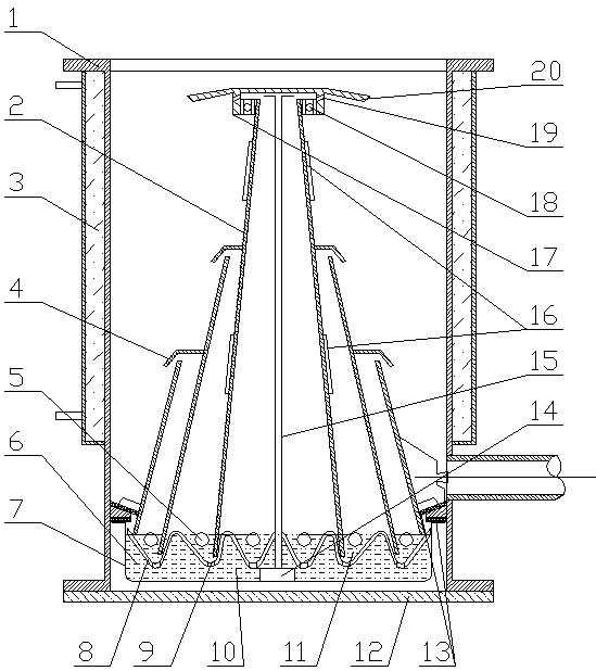
[0037] Embodiment 2: the embodiment of another kind of diffusion pump of the present invention is such as figure 2 As shown, compared with Embodiment 1, a submersible pump 14 and an oil pipe 15 are added in the oil storage area 10; the submersible pump 14 is connected with the oil pipe 15, and the top of the oil pipe 15 is located at the nozzle of the primary injection system; the diffusion pump stops When vacuuming, first turn off the vacuum valve and the power supply of the evaporation system 7, the heater 5 and the heating device 16 stop heating, then turn on the submersible pump 14, the pump oil 6 in the oil storage area 10 is injected at the nozzle through the oil pipe 15, and a part of the pump The oil 6 is sprayed onto the inner wall of the pump body 1 and cooled by the cooling system 3. Another part of the pump oil 6 is sprayed on the pump core 2 to cool the pump core 2. The pump oil 6 cooled by the cooling system 3 and the The pump oil 6 warmed up by the core 2 and t...

Embodiment 3

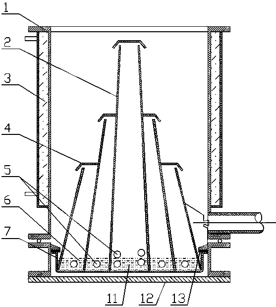
[0038] Embodiment 3: the embodiment of another kind of diffusion pump of the present invention is as image 3 As shown, compared with Example 1, the difference is that the pump body 1 is divided into upper and lower sections, and the two sections are connected and sealed by a silicone rubber sealing ring to further block the heat flow between the evaporation system 7 and the cooling system. It is also convenient for the assembly and maintenance of the diffusion pump; there is no intermediate partition in the evaporator, and the pump core 2 is directly installed in the evaporator; the evaporator is suspended and installed in the lower section of the pump body 1 through the heat insulating pad 13, and the periphery of the evaporator is installed through a special The pipeline uses a backing pump to form a vacuum chamber to achieve thermal insulation.


PUM


Abstract

A diffusion pump comprises a pump body, pump oil, a pump core, an evaporation system, a cooling system, an injection system and a control system. The evaporation system is mounted at the bottom of thepump body in a mode of suspension, or heat insulation or heat isolation, and adopts the heating mode of instant heating or floating instant heating to heat the pump oil in a heating area to enable the pump oil to be evaporated instantly into steam. Fixed spraying heads or rotating spraying heads are arranged at the top of a steam guiding pipe in the injection system, a set of nozzles which spraytowards the inclined lower portion is evenly arranged on the periphery of each fixed spraying head, and the steam is sprayed out from the nozzles to form a rotating circinate airflow swirl. A series of nozzles are arranged on the peripheries of the rotating spraying heads, and the rotating spraying heads can rotate at a high speed through counter-acting force generated when the nozzles spray the steam. Heating devices are mounted on the pump core or on the steam guiding pipe, thus the temperatures of the pump core and the steam can be increased, the speed rate and kinetic energy of steam spraying are increased, and quick starting of the diffusion pump can be achieved.

Description

technical field [0001] The invention relates to the field of vacuum pumps, in particular to a diffusion pump. Background technique [0002] Vacuum diffusion pump is currently one of the most widely and most important tools for obtaining high vacuum. Diffusion pump is mainly composed of pump body, pump oil, pump core, evaporation system, cooling system, injection system and control system. Under the low vacuum condition formed by the vacuum pump, the evaporation system makes the pump oil boil and evaporate, and the generated steam is ejected through the injection system at a very high speed, so that the gas molecules in the upper part of the pump diffuse into the steam, and the oil vapor flows through the pump through the cooling system. The lower part is condensed, and the released gas molecules are sucked away by the backing pump, and the condensed pump oil is returned to the evaporation system to be reheated, so that the cycle works to achieve the purpose of pumping. The ...

Claims


Application Information

Patent Timeline
Patent Type & Authority Applications(China)
IPC IPC(8): F04F9/00
CPCF04F9/00
Inventor 戴长虹
Owner 戴海玥
Why Eureka
Try Eureka