
Microstrip patch antenna based on SIW resonant cavity loading

A microstrip patch antenna, resonant cavity technology, applied in the direction of the antenna grounding switch structure connection, waveguide, circuit, etc., can solve the problems of reduced antenna radiation efficiency, complex structure design, high manufacturing cost, and achieve wide bandwidth and good radiation characteristics. , the effect of low production cost

Active Publication Date: 2018-11-09
NANJING UNIV OF SCI & TECH
View PDF11 Cites 1 Cited by
  • Summary
  • Abstract
  • Description
  • Claims
  • Application Information

AI Technical Summary

Problems solved by technology

[0003] Increase the thickness of the dielectric substrate or reduce the relative permittivity of the dielectric substrate. Although this method can increase the bandwidth of the patch antenna, the radiation efficiency of the antenna will also be greatly reduced; in 2014, Quan Wei Lin, Hang Wong, Xiu Yin Zhang and Hau Wah Lai published "Printed Meandering Probe-Fed Circularly Polarized Patch Antenna WithWide Bandwidth" on IEEE ANTENNAS AND WIRELESS PROPAGATION LETTERS, and proposed to use a meandering probe feeding structure and use a four-layer dielectric substrate to obtain 42.3% impedance matching bandwidth, but the antenna radiation pattern of this design changes with the frequency and has a high cross-polarization, the cross-polarization reaches -15dB, the structure is complex, and the manufacturing cost is high
[0004] In 2015, Shuo Liu, Shi-Shan Qi, Wen Wu, and Da-Gang Fang published "Single-Feed Dual-Band Single / Dual-Beam U-Slot Antenna for Wireless Communication Application" on IEEE TRANSACTIONSON ANTENNAS AND PROPAGATION, through Etching U-shaped grooves on the radiation patch has obtained 7.3% of the antenna bandwidth, but this method also has high cross-polarization, which reaches -18dB, and the structural design is complicated and the manufacturing cost is high
[0005] In summary, the existing methods for expanding the bandwidth of microstrip patch antennas have various limitations, and the structure is complex and the manufacturing cost is high.

Method used


Image

  • Microstrip patch antenna based on SIW resonant cavity loading
  • Microstrip patch antenna based on SIW resonant cavity loading
  • Microstrip patch antenna based on SIW resonant cavity loading

Examples


Embodiment 1

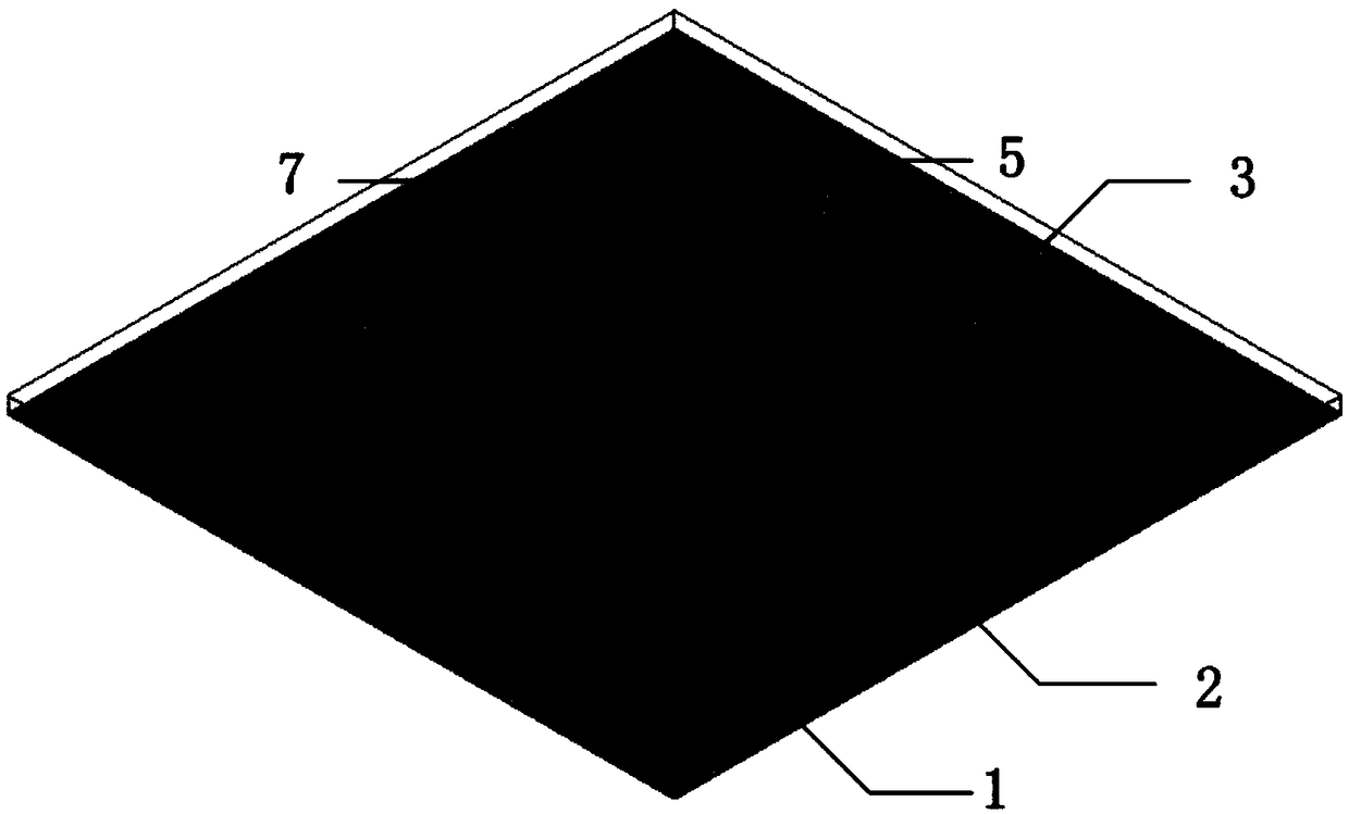
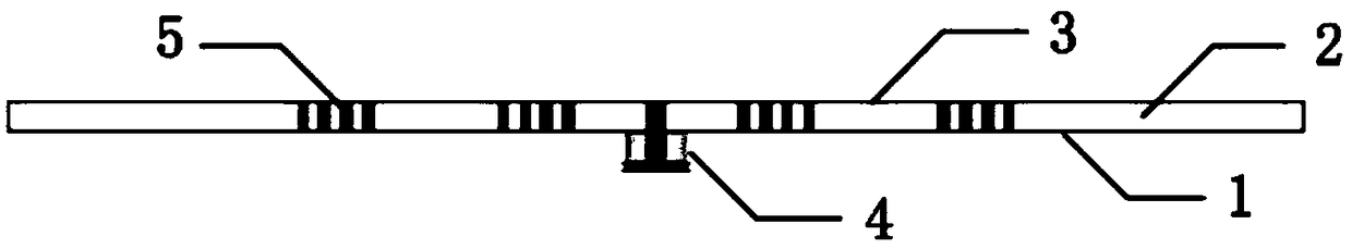
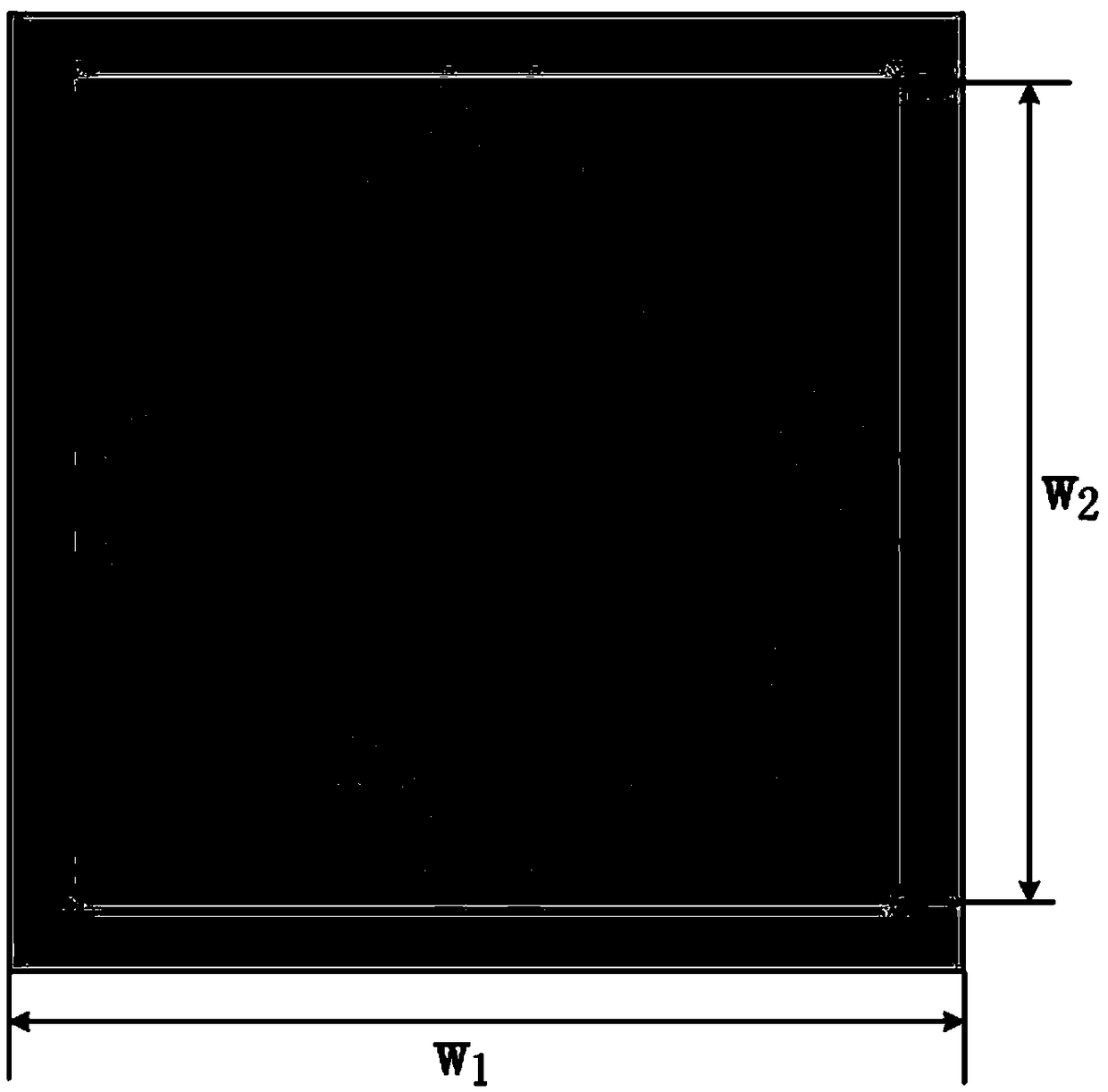
[0032] Such as figure 2 As shown, a microstrip patch antenna based on SIW resonant cavity loading includes a metal formation layer 1, a dielectric substrate 2, a square patch layer 3 and an SMA coaxial excitation input port 4 stacked from bottom to top. The dielectric substrate 2 is provided with a metallized through-hole array 5, and the metallized through-hole array 5 together with the square patch layer 3 and the metal ground layer 1 forms a square substrate integrated waveguide SIW cavity 7, and the metallized through-hole array 5 That is, the four sides of the square substrate integrated waveguide cavity 7, the square substrate integrated waveguide cavity 7 and the square patch layer 3 share a center point, and the angular displacement between the two is 45°, the square substrate integrated waveguide cavity 7 There are coupling windows 6 of the same size in the middle of the four sides.

[0033] Such as image 3 As shown, this embodiment is based on the simulation mode...


PUM

PropertyMeasurementUnit
Side length sizeaaaaaaaaaa
Diameteraaaaaaaaaa
Thicknessaaaaaaaaaa

Abstract

The invention discloses a microstrip patch antenna based on SIW resonant cavity loading. The microstrip patch antenna comprises a metal ground layer, a dielectric substrate, a square patch layer and acenter-fed SMA coaxial excitation input port stacked from bottom to top, wherein the dielectric substrate is provided with a metallized through hole array, the metallized through hole array, the square patch layer and the metal ground layer together form a square substrate integrated waveguide cavity, a new resonant point is introduced by loading the square substrate integrated waveguide cavity,and antenna bandwidth is enhanced. The microstrip patch antenna has advantages of simple and compact structure, low profile, easy integration and good directionality, can be applied to various high frequency bands, especially millimeter wave circuit design, and has wide application prospects.

Description

technical field [0001] The invention belongs to antenna design technology, in particular to a microstrip patch antenna loaded based on SIW resonant cavity. Background technique [0002] With the development of microwave technology, people have higher and higher requirements for the integration and miniaturization of microwave systems and microwave devices. Microstrip patch antennas have been deeply studied because of their low profile, easy integration, and low cost. It is the most commonly used form in microwave and millimeter wave circuits. However, in microwave and millimeter wave systems, it is difficult for microstrip antennas to obtain high gain and wide operating frequency band. In the prior art, there are mainly the following methods for widening the antenna bandwidth: using dielectric substrates of special materials, adding impedance matching networks, increasing substrate thickness, using multi-layer dielectric substrates and coplanar parasitic patches, etc. [00...

Claims


Application Information

Patent Timeline
IPC IPC(8): H01Q1/38H01Q1/50H01P3/12
CPCH01P3/121H01Q1/38H01Q1/50
Inventor 杨梦妮王建朋王诗言储呈伟
Owner NANJING UNIV OF SCI & TECH
Learn More