
CO2 emission reduction system and method synergized with hydrogen production by step-by-step conversion of biomass energy

A technology of biomass energy and biomass, which is applied in the field of biomass energy step-by-step hydrogen production and CO2 emission reduction system, which can solve the problems of small processing capacity, retention, and large energy

Active Publication Date: 2018-11-20
SOUTHEAST UNIV
View PDF4 Cites 6 Cited by
  • Summary
  • Abstract
  • Description
  • Claims
  • Application Information

AI Technical Summary

Problems solved by technology

Among them, the photoelectrocatalysis of CO 2 The processing capacity of gas is small, and it is mainly in the laboratory stage at present; while CO 2 The temperature required for pyrolysis is relatively high, usually higher than 1000°C, which not only consumes a lot of energy, but also has extremely strict requirements on equipment, and high temperature will inevitably cause more energy loss
At present, there is no use of biomass tar and biochar as composite reducing agents to reduce CO by photothermal method. 2 research report

Method used


Image

  • CO2 emission reduction system and method synergized with hydrogen production by step-by-step conversion of biomass energy
  • CO2 emission reduction system and method synergized with hydrogen production by step-by-step conversion of biomass energy
  • CO2 emission reduction system and method synergized with hydrogen production by step-by-step conversion of biomass energy

Examples


Embodiment 1

[0049] Include the following steps:

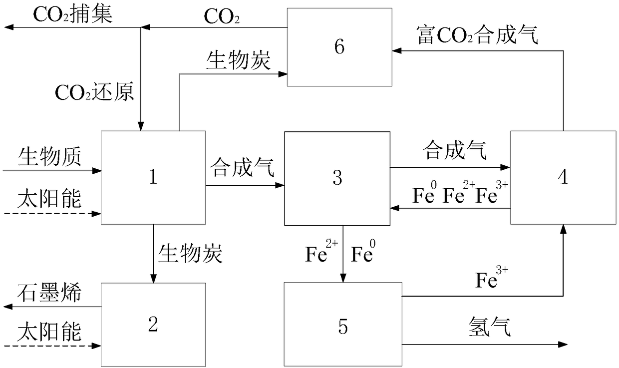
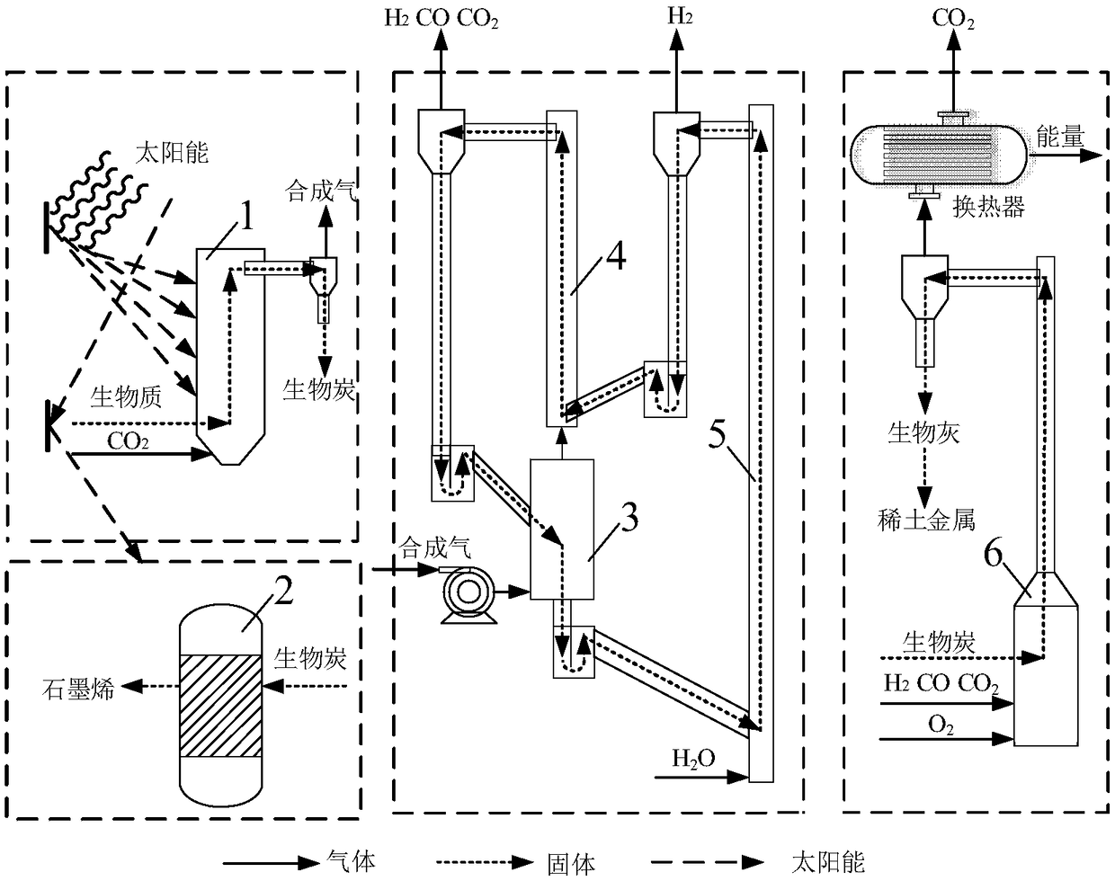
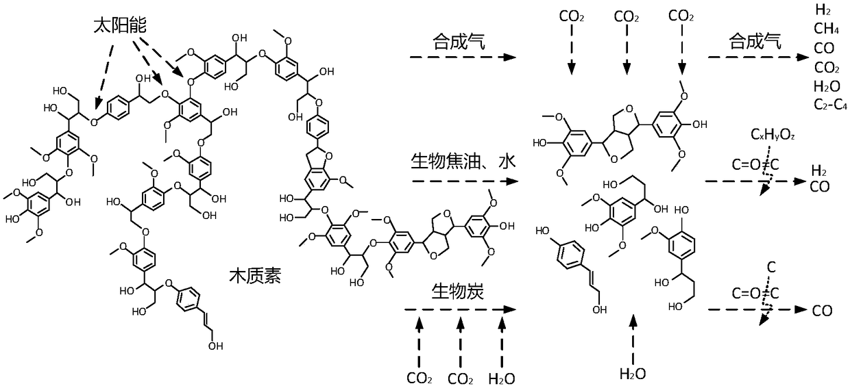
[0050] 1) CO 2 In the photothermal reduction device, in CO 2 Biomass gasification as a gasification medium at 800°C to obtain syngas and biochar;

[0051] 2) The synthesis gas is passed into the primary fuel reactor and the secondary fuel reactor and is gradually oxidized by the oxygen carrier, and the temperature is controlled at 950°C;

[0052] 3) The oxygen carrier reduced by the synthesis gas is sent to the steam reactor through the U valve, and is oxidized by water vapor at 800°C to produce hydrogen;

[0053] 4) 10% biochar with a high degree of graphitization is used for graphene preparation, and graphene oxide is reduced at 650° C. under hydrogen conditions to obtain reduced graphene oxide;

[0054] 5) The remaining 90% of the biochar is sent to the combustion furnace to assist the heating device for combustion, while capturing CO 2gas, and will capture 4% CO in the gas 2 It is passed into a photothermal reduction device as a g...

Embodiment 2

[0056] 1) CO 2 In the photothermal reduction device, in CO 2 Biomass gasification as a gasification medium at 880°C to obtain syngas and biochar;

[0057] 2) The synthesis gas is passed into the primary fuel reactor and the secondary fuel reactor and is gradually oxidized by the oxygen carrier, and the temperature is controlled at 920°C;

[0058] 3) The oxygen carrier reduced by the synthesis gas is sent to the steam reactor through the U valve, and is oxidized by water vapor at 850°C to produce hydrogen;

[0059] 4) 25% biochar with a high degree of graphitization is used for graphene preparation, and graphene oxide is reduced at 750°C and hydrogen to obtain reduced graphene oxide;

[0060] 5) The remaining 75% of the biochar is sent to the combustion furnace to assist the heating device to burn, and at the same time capture CO 2 gas, and will capture 5% CO in the gas 2 It is passed into a photothermal reduction device as a gasification medium for biomass conversion.

Embodiment 3

[0062] 1) CO 2 In the photothermal reduction device, in CO 2 As a gasification medium, biomass gasification is carried out at 900°C to obtain syngas and biochar;

[0063] 2) Pass the synthesis gas into the primary fuel reactor and the secondary fuel reactor and be oxidized by the oxygen carrier step by step, and the temperature is controlled at 900°C;

[0064] 3) The oxygen carrier reduced by the synthesis gas is sent to the steam reactor through the U valve, and is oxidized by water vapor at 900°C to produce hydrogen;

[0065] 4) 15% biochar with a high degree of graphitization is used for graphene preparation, and graphene oxide is reduced at 720°C and hydrogen to obtain reduced graphene oxide;

[0066] 5) The remaining 85% of the biochar is sent to the combustion furnace to assist the heating device to burn, and at the same time capture CO 2 gas, and will capture 8% CO in the gas 2 It is passed into a photothermal reduction device as a gasification medium for biomass co...


PUM


Abstract

The invention discloses a CO2 emission reduction system and method synergized with hydrogen production by step-by-step conversion of biomass energy. The system comprises a CO2 photothermal reduction device, a graphene photothermal reduction furnace, a chemical chain hydrogen production device and a combustion furnace auxiliary heating device. High-efficiency conversion of biomass energy into synthesis gas, preparation of reduced graphene oxide and continuous and stable preparation of high-quality hydrogen are realized respectively by adopting renewable biomass as a raw material and utilizing aconcentrating solar energy technology, a novel graphene oxide photothermal reduction technology and a multi-stage fuel reactor chemical chain hydrogen production technology. The energy input of the system is inexhaustible solar energy, renewable biomass energy with zero-carbon emission in a life cycle, and high-quality hydrogen and graphene materials are prepared continuously and efficiently on the premise of ensuring the system self-heating, and the step-by-step conversion and utilization of non-fossil energy as well as the continuous emission reduction, fixation and reuse of CO2 gas under self-heating conditions of the system are realized.

Description

technical field [0001] The invention relates to a step-by-step conversion of biomass energy for hydrogen production and synergistic CO 2 The emission reduction system and method belong to the field of combustion and chemical technology. Background technique [0002] With the consumption of fossil energy and CO 2 With increasing greenhouse gas emissions, how to deal with CO 2 Catalytic reduction and reuse of gas has become the development direction of green energy and chemistry in the future, and has attracted more and more attention. Existing CO 2 Reduction methods mainly include photocatalysis, electrocatalysis, photoelectrocatalysis, CO 2 pyrolysis etc. Among them, the photoelectrocatalysis of CO 2 The processing capacity of gas is small, and it is mainly in the laboratory stage at present; while CO 2 The temperature required for pyrolysis is relatively high, usually higher than 1000°C, which not only consumes a lot of energy, but also has extremely strict requireme...

Claims


Application Information

Patent Timeline
Patent Type & Authority Applications(China)
IPC IPC(8): C01B32/184C01B3/06C01B3/10C01B32/50C10J3/56C10J3/72
CPCC01B3/063C01B3/105C10J3/56C10J3/72C10J2300/092C10J2300/0969C10J2300/1292C10J2300/1606C10J2300/1612C10J2300/1637C10J2300/1807C01B32/184C01B32/50Y02E60/36Y02P20/133
Inventor 孙朝向文国陈时熠段伦博
Owner SOUTHEAST UNIV
Learn More