
Ink-jet printing method for micro-structure of quantum dot light guide plate mesh

A light guide plate dot and inkjet printing technology, which is applied in the field of microcircuits, can solve the problems of affecting the light output effect of the device, increasing the difficulty of printing, and poor controllability of droplet size, so as to prevent dot collapse and dot bottom size from being too large, and reduce circulation The effect of printing times and saving printing consumables

Active Publication Date: 2018-11-27
FUZHOU UNIV
View PDF4 Cites 9 Cited by
  • Summary
  • Abstract
  • Description
  • Claims
  • Application Information

AI Technical Summary

Problems solved by technology

[0004] In order to meet the light uniformity and brightness of the liquid crystal display, the dots on the light guide plate need a certain distribution density and size, but inkjet printing is a solution processing technology, which has poor control over the droplet size.
Especially in order to form a three-dimensional spherical crown dot structure of a certain size, multiple cycles of deposition are required, and multiple depositions of the solution will inevitably cause the dots to collapse. At the same time, increasing the number of printing cycles will cause the dot size to be too large, although it can be achieved by increasing the printing. The viscosity of the quantum dot solution can improve this problem to a certain extent, but it cannot completely control it, and the final result will affect the light-emitting effect of the device; and simply improving this phenomenon by increasing the solution viscosity will also reduce the quantum Printability of dot solution, increasing difficulty of printing
Patent CN106154400A proposes a method for improving inkjet printing quantum dot light guide network, but it mainly studies the influence of the substrate, and does not propose an effective solution to this important phenomenon

Method used


Image

  • Ink-jet printing method for micro-structure of quantum dot light guide plate mesh
  • Ink-jet printing method for micro-structure of quantum dot light guide plate mesh
  • Ink-jet printing method for micro-structure of quantum dot light guide plate mesh

Examples


Embodiment

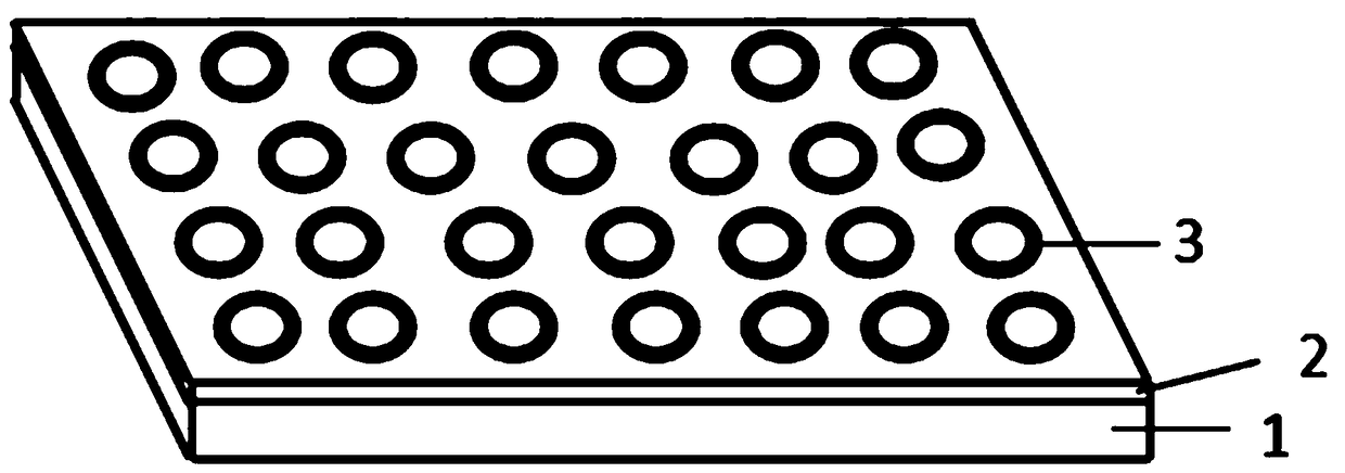
[0056] Taking specific production as an example, the production process has the following steps in sequence;

[0057] Step 1. The material of the light guide plate used in this example is polymethyl methacrylate (PMMA), its specific gravity is 1.20, the refractive index is 1.49, and the light transmittance is 92%;

[0058] Specifically, the thickness of the light guide plate is 1.5-3mm, and the size is 70mm*120mm;

[0059] Step 2. In order to deposit ink droplets on the light guide substrate 1 to form standard spherical crown scattering dots, the light guide substrate 1 is pretreated;

[0060] Specifically, scrape-coat PMMA solution on the light guide substrate 1, and dry it at room temperature for 24 hours to form a PMMA film 2 with a thickness of 80-100 nm;

[0061] Specifically, the concentration of used PMMA solution is 30mg / ml-50mg / ml, and used solvent is one or more in low polarity organic solvents such as toluene, chlorobenzene, chloroform, but not limited to these; D...


PUM

PropertyMeasurementUnit
Viscosityaaaaaaaaaa
Viscosityaaaaaaaaaa
Surface tensionaaaaaaaaaa

Abstract

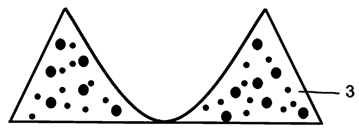
The invention provides an ink-jet printing method for a micro-structure of a quantum dot light guide plate mesh. The printing method comprises the following steps in turn: A1) performing ink-jet printing on a light guide plate by adopting a first quantum dot ink solvent containing quantum dot ink and utilizing a coffee-ring effect to generate an annular bank structure on the surface of the light guide plate; A2) curing the bank structure; A3) printing the light guide plate by adopting a second quantum dot ink solvent containing the quantum dot ink and forming a spherical crown structure by thebank structure; and A4) curing the spherical crown structure, thereby forming a spherical crown micro-structure of the light guide plate mesh. According to the invention, the condition of three-dimensional structure collapse in a general mesh printing process can be improved, the mesh controllability can be increased and the light guiding effect of the quantum dot light guide plate is finally promoted.

Description

technical field [0001] The invention relates to the technical field of microcircuits, in particular to a method for inkjet printing the dot microstructure of a quantum dot light guide plate. Background technique [0002] For the widely used liquid crystal display device, the liquid crystal cannot emit light, and the backlight module is one of the main components of the liquid crystal display device. For commonly used edge-type backlight modules, in order to achieve the uniformity of light output, the microstructure of the scattering dots on the lower surface of the light guide substrate of the light guide plate plays a decisive role. [0003] Quantum dots are a semiconductor material with a particle size of 1-10nm, which has a narrow half-maximum spectral width and adjustable luminescence spectrum. The red and green quantum dots are directly mixed into the scattering dots on the lower surface of the light guide plate, and then the blue side light source and the red and gree...

Claims


Application Information

Patent Timeline
IPC IPC(8): B29C64/124B33Y10/00B33Y70/00G02B6/00
CPCB29C64/124B33Y10/00B33Y70/00G02B6/0043G02B6/0065
Inventor 叶芸郭太良徐胜陈恩果孙磊雷霄霄刘欣谢洪兴
Owner FUZHOU UNIV
Learn More