Oil sludge cracking device

A cracking device and oil sludge technology, which is applied in the petroleum industry, hydrocarbon oil treatment, sludge treatment by pyrolysis, etc., can solve the problems of difficult dehydration, high cost of treatment process, secondary pollution, etc., so as to improve the utilization rate of heat and reduce The effect of producing secondary pollution and increasing the cracking speed

Active Publication Date: 2018-11-30
NIUTECH ENVIRONMENT TECHNOLOGY CORPORATION
View PDF4 Cites 9 Cited by
  • Summary
  • Abstract
  • Description
  • Claims
  • Application Information

AI Technical Summary

Problems solved by technology

However, many of the above methods have problems such as high processing cost, complicated process equipment, low efficiency, and secondary pollution in actual large-scale industrial applications, which limit their further use.
It is a good choice to treat oil sludge by high-temperature cracking. However, due to the characteristics of oil sludge with high oil content, high viscosity, fine particles, and difficult dehydration, there is a lack of corresponding effective oil sludge cracking equipment in the prior art.

Method used


Image

  • Oil sludge cracking device
  • Oil sludge cracking device

Examples


Embodiment 1

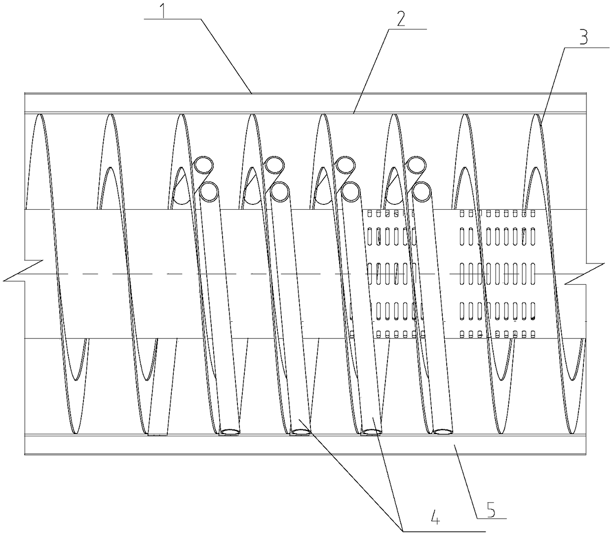
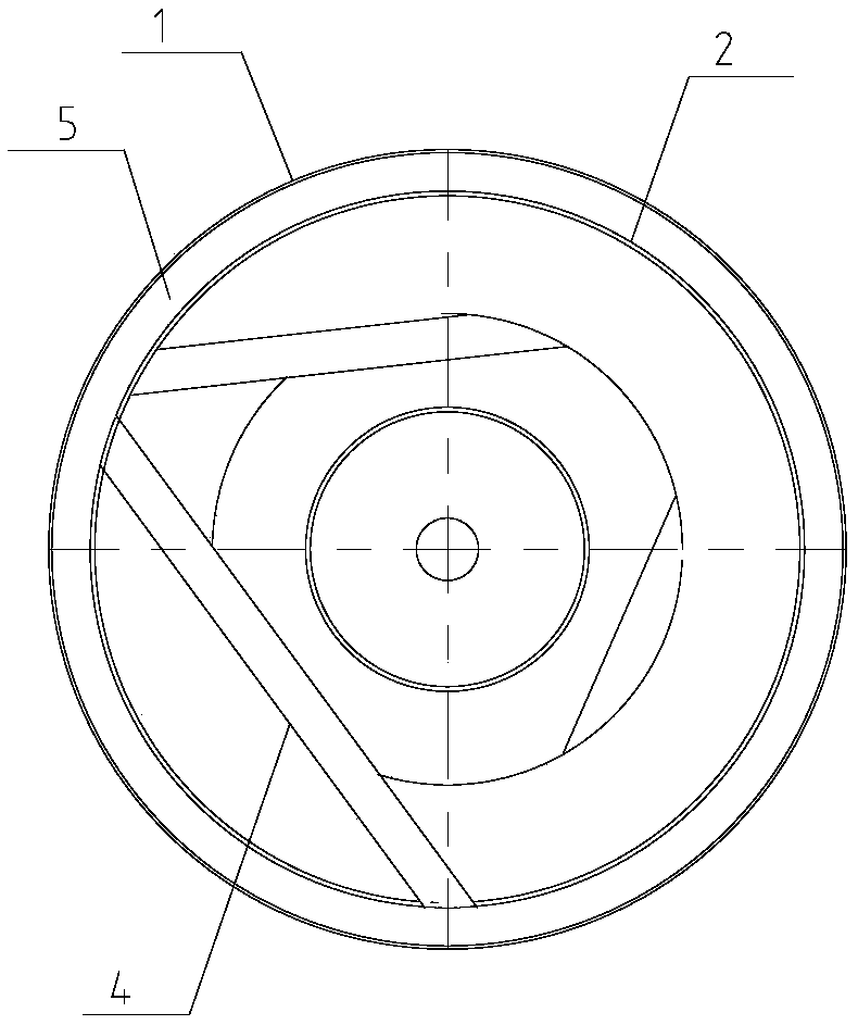
[0015] An oil sludge cracking device comprises an outer cylinder body and an inner cylinder body, the inner wall of the inner cylinder is provided with a spiral conveyor belt, and a heat conduction pipe is arranged on the spiral conveyor belt.

[0016] The heat pipe is a hollow pipe.

[0017] A solid heat carrier is dispersed in the inner cylinder.

Embodiment 2

[0019] An oil sludge cracking device comprises an outer cylinder body and an inner cylinder body, the inner wall of the inner cylinder is provided with a spiral conveyor belt, and a heat conduction pipe is arranged on the spiral conveyor belt.

[0020] Heat conduction pipes are uniformly arranged on each pitch of the spiral conveyor belt. Each pitch is provided with a heat pipe.

[0021] The heat pipe is a hollow pipe.

[0022] A solid heat carrier is dispersed in the inner cylinder.

[0023] The solid heat carrier is a non-metallic sphere.

[0024] The diameter of the non-metallic sphere is 5-25mm.

Embodiment 3

[0026] An oil sludge cracking device comprises an outer cylinder body and an inner cylinder body, the inner wall of the inner cylinder is provided with a spiral conveyor belt, and a heat conduction pipe is arranged on the spiral conveyor belt.

[0027] Heat conduction pipes are uniformly arranged on each pitch of the spiral conveyor belt. Two heat pipes are arranged on each pitch.

[0028] The heat pipe is a hollow pipe.

[0029] A solid heat carrier is dispersed in the inner cylinder.

[0030] The solid heat carrier is a metal sphere.

[0031] The diameter of the metal sphere is 5-50mm.


PUM

PropertyMeasurementUnit
diameteraaaaaaaaaa
diameteraaaaaaaaaa

Abstract

The invention belongs to the technical field of environmental protection, and particularly relates to an oil sludge cracking device. The oil sludge cracking device comprises an outer cylinder body andan inner cylinder body; a spiral conveyer belt is arranged on the inner wall of the inner cylinder body; and heat conduction pipes are arranged on the spiral conveyer belt. Through the adoption of the device provided by the invention, the heat exchange area in an oil sludge cracking process is enlarged, and the heat exchange efficiency is improved, so that the utilization rate of heat is greatlyimproved. The cracking speed of the oil sludge is increased at a relatively low temperature, oil in the oil sludge is fully recycled, and the amount of residual oil in treated soil reaches the national standard, so that treatment and application of reduction, harmlessness and reclamation of oil sludge are realized, no secondary pollution is generated, and the device is economical, is friendly to the environment and is safe.

Description

technical field [0001] The invention belongs to the technical field of environmental protection, and in particular relates to an oil sludge cracking device. Background technique [0002] Oily sludge is the abbreviation of oily sludge. It is an oily solid waste produced in the process of oil extraction, transportation, refining and oily sewage treatment. The oily sludge generally has an oil content of 10-50% or higher, and a water content of more than 30%. , In my country's petrochemical industry, an average of more than 800,000 tons of oily sludge is produced every year. The treatment of this part of sludge is a long-term problem in my country's petrochemical field. At present, there are more than ten kinds of sludge treatment technologies at home and abroad, including landfill, profile injection into formation, solidification treatment, thermal desorption, solvent extraction, incineration and coking pyrolysis, biological treatment, and comprehensive utilization. However, ma...

Claims


Application Information

Patent Timeline
Patent Type & Authority Applications(China)
IPC IPC(8): C02F11/10C10G1/00
CPCC10G1/00C02F11/10C10G2300/1003Y02W10/40C10G1/02C02F2103/365C02F2101/32C10B55/00C10B55/02C10B47/44C10B49/20C10B51/00C10B55/08
Inventor 牛晓璐韩国乾张海敏李宗才牛杰童兰英时圣玉鲁锋牛斌
Owner NIUTECH ENVIRONMENT TECHNOLOGY CORPORATION
Why Eureka
Try Eureka