
Thermal interface material based on composite thermal-conduction network of low-melting-point metals and thermal-conduction particles, and preparation method of thermal interface material

A low-melting-point metal and thermal interface material technology, applied in the field of thermal interface materials, can solve the problems of poor thermal conductivity and difficult to meet the heat dissipation requirements of high-performance electronic components, and achieve high thermal conductivity, low interface thermal resistance, good elasticity and The effect of softness

Active Publication Date: 2018-11-30
INST OF METAL RESEARCH - CHINESE ACAD OF SCI
View PDF6 Cites 19 Cited by
  • Summary
  • Abstract
  • Description
  • Claims
  • Application Information

AI Technical Summary

Problems solved by technology

[0003] Traditional thermal interface materials include thermally conductive silicone grease, phase change materials, and thermally conductive silica gel sheets. They are usually composed of polymer materials and thermally conductive particles. The huge thermal resistance between the thermally conductive particles determines the poor thermal conductivity of traditional thermal interface materials. It has been difficult to meet the increasingly demanding heat dissipation requirements of high-performance electronic components

Method used


Image

  • Thermal interface material based on composite thermal-conduction network of low-melting-point metals and thermal-conduction particles, and preparation method of thermal interface material
  • Thermal interface material based on composite thermal-conduction network of low-melting-point metals and thermal-conduction particles, and preparation method of thermal interface material
  • Thermal interface material based on composite thermal-conduction network of low-melting-point metals and thermal-conduction particles, and preparation method of thermal interface material

Examples


Embodiment 1

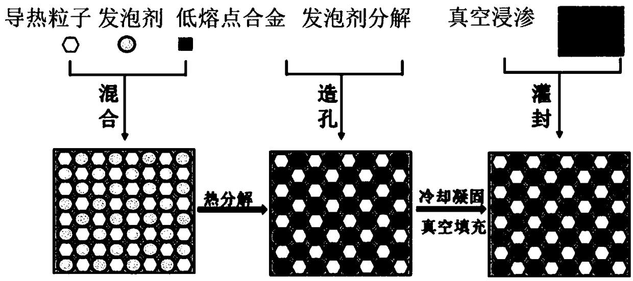
[0029] The preparation principle of the thermal interface material in this example is as follows: figure 1 As shown, the specific process is as follows:

[0030] (1) Preparation of low-melting point alloy: mix gallium (purity 99.99%) and titanium powder (1600 mesh, purity 99.99%) according to the mass ratio of 99:1, fully stir, and place in a constant temperature furnace at 200°C for 2 hours to obtain a low melting point alloy. Melting point alloy - gallium titanium alloy.

[0031] (2) Take titanium-coated diamond particles (325 mesh, vacuum-evaporated titanium) and mix them with gallium-titanium alloy according to the mass ratio of 1:1.6, and place them in a mortar, grind and stir repeatedly for 15 minutes, so that the gallium and titanium-coated diamond particles are completely Wet and mix thoroughly, and keep it in a constant temperature furnace at 200°C for 2 hours to form a stronger metallurgical bond between gallium and titanium.

[0032] (3) Making foaming agent: Grin...

Embodiment 2

[0039] (1) Mix low-melting-point gallium metal (purity 99.99%) and thermally conductive copper particles (150 mesh, purity 99.99%) at a mass ratio of 1:2, stir well, and keep warm at 50°C for 10 minutes. Production of foaming agent: Grind ammonium bicarbonate into fine particles, pass through stainless steel standard sieves of different meshes, and sieve to obtain ammonium bicarbonate particles with a particle size of 34-50 μm.

[0040](2) Add the prepared foaming agent to the mixture prepared in the first step according to the mass ratio of 5%, fully mix, and then place the mixture in the mold, with 1.16×10 6 The pressure of Pa compacts and shapes the material.

[0041] (3) Place the sample prepared in the third step in a holding furnace, first heat it at 80°C for 8 hours, and then hold it at 120°C for 2 hours to ensure that the ammonium bicarbonate is completely decomposed, thereby obtaining a three-dimensional network structure material with continuous pores.

[0042] (4) ...

Embodiment 3

[0046] The preparation process of the thermal interface material in this embodiment is as follows:

[0047] (1) Electroless copper plating on the surface of boron nitride (particle size ≈ 5 μm, purity 99.9%), boron nitride particles with low melting point metal gallium (purity 99.99%) and metallization (copper-coated boron nitride) Mix according to the mass ratio of 1:1, stir well, and keep warm at 50°C for 10min.

[0048] (2) Making foaming agent: Grinding ammonium bicarbonate into fine particles, passing through stainless steel standard sieves with different meshes, sieving to obtain ammonium bicarbonate particles with a particle size of 34-50 μm.

[0049] (3) Add the prepared foaming agent to the mixture prepared in the first step according to the mass ratio of 5%, fully mix, and then place the mixture in the mold, with 1.16×10 6 The pressure of Pa compacts and shapes the material.

[0050] (4) Place the sample prepared in the third step in a holding furnace, first heat i...


PUM

PropertyMeasurementUnit
Particle sizeaaaaaaaaaa
Thermal diffusivityaaaaaaaaaa
Densityaaaaaaaaaa

Abstract

The invention discloses a thermal interface material based on a composite thermal-conduction network of low-melting-point metals and thermal-conduction particles, and a preparation method of the thermal interface material, and belongs to the technical field of thermal interface materials. The material is prepared by taking low-melting-point metals, thermal-conduction particles, a foaming agent, and a high-molecular polymer as raw materials and adopting the technical processes of metallurgical interconnection of the low-melting-point metals and the thermal-conduction particles, high-temperaturedecomposition and pore-forming of the foaming agent, vacuum impregnation of the high-molecular polymer, and the like. The material is provided with an extremely high thermal conductivity through high-efficiency three-dimensional thermal-conduction channels constructed by the low-melting-point metals and the thermal-conduction particles; high elasticity and softness of the material are ensured through the use of the high-molecular polymer and the low-melting-point metals; in a use process, metallurgical interconnection is formed at the interface of the low-melting-point metals and a metal substrate, and the high-molecular polymer has an adhesive effect with the substrate, so that the two connection mode provide extremely low interface resistance and restrict the overflow problem of the low-melting-point metals.

Description

technical field [0001] The invention relates to the technical field of thermal interface materials, in particular to a thermal interface material based on a composite heat conduction network of low melting point metal\heat conduction particles and a preparation method thereof. Background technique [0002] With the high power, high assembly density and miniaturization of electronic components, the power density of electronic equipment has increased sharply, even reaching 100W / cm 2 s level. Temperature rise has an important impact on the working state and physical structure of the circuit, and usually changes the electrical parameters of active devices, and even causes the complete failure of electronic components. Therefore, how to effectively ensure the heat dissipation of electronic components has become a key factor restricting the further improvement of their performance and reliability. During the service process of electronic equipment, most of the heat needs to be d...

Claims


Application Information

Patent Timeline
IPC IPC(8): C08L83/04C08L27/18C08L25/06C08L63/00C08K3/08C08K9/02C08K3/04C08K3/38C08J9/08
CPCC08J9/0066C08J9/009C08J9/08C08J2203/02C08J2325/06C08J2327/18C08J2363/00C08J2383/04
Inventor 郭敬东位松周丽君
Owner INST OF METAL RESEARCH - CHINESE ACAD OF SCI
Learn More