T-type conversion circuit and corresponding three-phase conversion circuit and conversion device

A technology for converting circuits and circuit modules, which is applied to output power conversion devices, AC power input conversion to DC power output, electrical components, etc., can solve problems such as power device noise pollution, large device stress, and complex design, and achieve output The filter parameter requirements are lowered, the power density of the product is improved, and the structure is simple and compact.

Active Publication Date: 2018-12-07
KEHUA DATA CO LTD
View PDF4 Cites 2 Cited by
  • Summary
  • Abstract
  • Description
  • Claims
  • Application Information

AI Technical Summary

Problems solved by technology

[0004] 1. The power device (controllable switching device) has a large loss; it causes the temperature of the power device to rise, not only makes the operating frequency unable to increase, but also the current and voltage capacity of the power device cannot reach the rated index, so that the power device cannot operate under rated conditions , thus restricting the application of the three-level topology;
[0005] 2. Power devices are prone to secondary breakdown; under inductive load conditions, there is a peak voltage when the power device is turned off; and under capacitive load conditions, there is a peak current when the power device is turned on; thus it is easy to cause secondary breakdown, Greatly endanger the safe operation of power devices, making it necessary to design a larger safe operating area (SOA);
[0006] 3. Generate large EMI electromagnetic interference; when operating at high frequency, the parasitic capacitance between the poles of the power device itself is an extremely important parameter
This kind of inter-electrode capacitance will produce two unfavorable factors in the switching process of power devices: (1) When the power device is turned on at high voltage, the energy stored in the inter-electrode parasitic capacitance is absorbed and dissipated by the device itself, which will inevitably cause temperature rise, and the frequency The higher the temperature rise, the more serious it will be; (2) dv / dt will be coupled to the output terminal when the inter-electrode capacitor voltage is converted, generating electromagnetic interference and making the system unstable
In addition, inter-electrode capacitance and stray inductance in the circuit will oscillate and interfere with the normal operation of the system;
[0007] 4. As a result, the circuit topology is very sensitive to the parasitic parameters of the power device; when the soft switch cannot be realized, there may be a problem of direct connection of the upper and lower bridge arms, and because the soft switch cannot be realized, the power device still has a turn-on delay time (dead time), and In the case of high frequency, in order to eliminate the influence of dead time on inverter performance, the corrective measures taken complicate the design of the whole system;
[0008] 5. It is necessary to design the absorption circuit, which is used to limit the di / dt when the power device is turned on and the dv / dt when it is turned off, so that the dynamic switching track can be reduced to the SOA of the DC safe area, so as to ensure the safe operation of the power device, but the absorption The circuit cannot eliminate switching losses, and it increases the design difficulty of the entire conversion device, and may also cause greater device stress due to the reverse recovery of the freewheeling diode and the mutual interference of the absorption circuit during the energy regeneration process;
[0009] 6. Power devices will generate noise pollution when switching at high frequencies, which will lead to higher requirements for the input and output filters of the conversion circuit

Method used


Image

  • T-type conversion circuit and corresponding three-phase conversion circuit and conversion device
  • T-type conversion circuit and corresponding three-phase conversion circuit and conversion device
  • T-type conversion circuit and corresponding three-phase conversion circuit and conversion device

Examples


Embodiment 2

[0101] In the second embodiment, the principle of realizing soft switching by the controllable switching device and the diode during the commutation process is similar to that of the first embodiment, and will not be described in detail here.

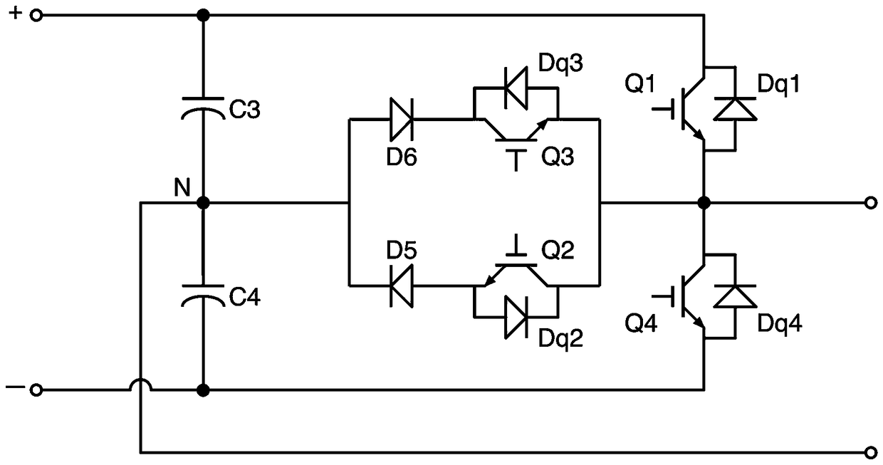
[0102] Image 6 A schematic circuit diagram of Embodiment 3 of the T-type conversion circuit in the present invention is shown. Such as Image 6 As shown, the third embodiment of the T-type conversion circuit includes two vertically arranged controllable switching devices, two horizontally arranged controllable switching devices, an inductor L, a first diode D1, and a second diode D2 , the third diode D3, the fourth diode D4, the fifth diode D5, the sixth diode D6, the first capacitor C1, the second capacitor C2, the third polarity capacitor C3 and the fourth polarity Capacitor C4.

[0103] The two vertically arranged controllable switching devices are respectively the first controllable switching device and the fourth controllable s...


PUM


Abstract

The invention discloses a T-type conversion circuit and a corresponding three-phase conversion circuit and a conversion device. In the T-type conversion circuit, by adding an inductor, four diodes andtwo capacitors in a T-type conversion circuit in the prior art, a controllable switching device and a diode device of the T-type conversion circuit can realize soft switching, and the power consumption of power devices and diode devices is reduced. The conversion device adopting the above-mentioned T-type conversion circuit combines components in the prior art with the newly-added components in the technical scheme by setting a first circuit module and a second circuit module, so that in a case that the internal circuit layout of the inverter / rectifier is not changed, the reconstruction costis greatly reduced, the topological structure is compact, and the busbar design is simple, which is extremely advantageous for electrical layout and structural design.

Description

technical field [0001] The invention relates to the field of electric energy conversion, in particular to a T-shaped conversion circuit. Background technique [0002] In the prior art, conversion circuits with a T-shaped layout have been widely used. The conversion circuit of T-shaped layout generally includes two vertically arranged controllable switching devices and two horizontally arranged controllable switching devices; the two vertically arranged controllable switching devices are connected in series, one end is connected to the positive bus, and the other end is connected to Negative bus bar; the connection point between two vertically arranged controllable switching devices is used as the input and output terminals of the conversion circuit; two horizontally arranged controllable switching devices are generally arranged on the middle bridge arm, and one end of the middle bridge arm is connected to Input and output terminals, the other end of the middle bridge arm is...

Claims


Application Information

Patent Timeline
Patent Type & Authority Applications(China)
IPC IPC(8): H02M7/797H02M1/44
CPCH02M1/44H02M7/797H02M7/487H02M1/0058H02M1/327Y02B70/10
Inventor 陈四雄陈成辉易龙强
Owner KEHUA DATA CO LTD
Why Eureka
Try Eureka