Water level monitoring device and monitoring method based on plastic fiber optic light time domain reflection

A technology of water level monitoring device and optical time domain reflection, which is applied in the direction of measuring device, lubrication indicating device, engine lubrication, etc., can solve problems such as difficult installation and maintenance, susceptibility to wind and waves, electromagnetic interference of charged components, etc. Continuous monitoring, easy transportation and maintenance, high precision and high resolution effect

Active Publication Date: 2018-12-11
HOHAI UNIV
View PDF7 Cites 4 Cited by
  • Summary
  • Abstract
  • Description
  • Claims
  • Application Information

AI Technical Summary

Problems solved by technology

Among them, the float-type water pressure gauge uses the float to rise and fall with the water level, and records through mechanical transmission. Pressure principle, using pressure sensitive elements for sensing, no need for well logging, high sensitivity, but greatly affected by environmental factors such as temperature, water leakage is prone to occur for a long time, and real-time performance is difficult to guarantee; ultrasonic water level gauges use sound waves to reflect water levels at different interfaces , is a non-contact measurement with reliable performance and stable operation, but there are measurement blind spots and is easily affected by wind and waves; the radar water level gauge uses radar waves to measure the distance on the water surface. It is actually a radar range finder with high accuracy, but is easily affected by floating Influenced by objects, etc., resulting in unreliable measurement results
In addition, the above-mentioned water level gauges generally have problems such as high cost, difficult installation and maintenance, and some live components are susceptible to electromagnetic interference and even damaged by lightning strikes.

Method used


Image

  • Water level monitoring device and monitoring method based on plastic fiber optic light time domain reflection
  • Water level monitoring device and monitoring method based on plastic fiber optic light time domain reflection
  • Water level monitoring device and monitoring method based on plastic fiber optic light time domain reflection

Examples


Embodiment Construction

[0033] The present invention is described in further detail now in conjunction with accompanying drawing. These drawings are all simplified schematic diagrams, which only illustrate the basic structure of the present invention in a schematic manner, so they only show the configurations related to the present invention.

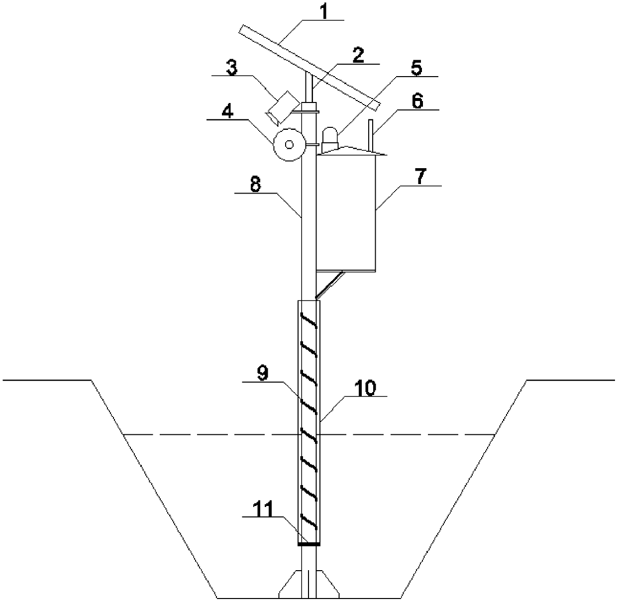
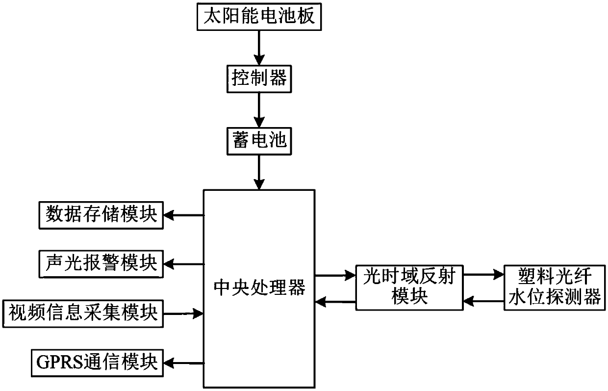
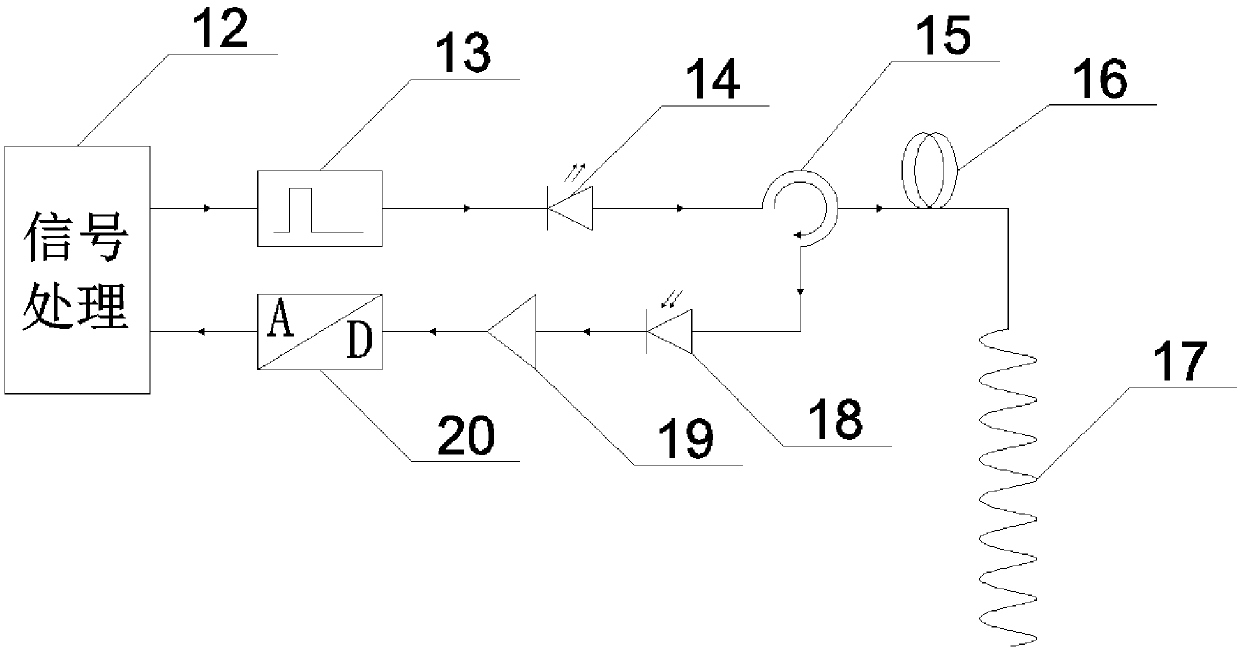
[0034] Such as Figure 1-Figure 4 As shown, the present invention includes the following feature parts: 1 is a solar panel, 2 is a solar panel support, 3 is a monitoring camera, 4 is a tweeter, 5 is a water level alarm, 6 is a GPRS antenna, 7 is a control box, and 8 is a vertical Rod, 9 is a plastic optical fiber, 10 is a protective cover, 11 is a filter screen, 12 is a signal processor, 13 is a pulse generator, 14 is a laser diode, 15 is a light direction coupler, 16 is a plastic optical fiber, 17 is a plastic optical fiber Probe, 18 is a photodetector, 19 is an amplifier, and 20 is an A / D analog-to-digital converter.

[0035] Figure 1-Figure 3 As shown, ...


PUM


Abstract

The invention relates to a water level monitoring device and monitoring method based on plastic fiber optic light time domain reflection. The device comprises a vertical rod fixed in a river bed of ato-be-tested water body, and further comprises a plastic fiber optic water level detector spirally winding around the position, close to the bottom, of the vertical rod, the position, close to the top, of the vertical rod is provided with a control box, the control box is internally provided with a control device, the top of the vertical rod is provided with a solar panel, the solar panel is communicated with the control device and provides power to the control device, the top of the control box is provided with a GPRS antenna, and the control device is communicated with the GPRS antenna and the plastic fiber optic water level detector respectively; the water level monitoring device and monitoring method based on the plastic fiber optic light time domain reflection can achieve remote and automatic monitoring and early warn dangerous situations.

Description

technical field [0001] The invention relates to a water level monitoring device and a monitoring method based on plastic optical fiber optical time domain reflection, belonging to the field of water level monitoring in the water conservancy industry. Background technique [0002] Water level is an important symbol reflecting the change of water body, the most basic observation quantity in hydrological survey, and one of the important environmental quantities for the safety monitoring of hydraulic structures. Water level data is the most important and basic hydrological information resource. It not only provides important data for water conservancy and water transportation, flood control and waterlogging control, but also provides indirect data for calculating other hydrological elements. Real-time on-line monitoring of the water level of the reservoir, so as to obtain the dynamic change information of the water level in a timely and accurate manner, can effectively avoid dan...

Claims


Application Information

Patent Timeline
Patent Type & Authority Applications(China)
IPC IPC(8): G01F23/292
CPCG01F23/292
Inventor 李涧鸣包腾飞高瑾瑾李慧朱茜曹恩华朱征刘甲奇
Owner HOHAI UNIV
Why Eureka
Try Eureka