A T-type rectifying circuit and a corresponding three-phase rectifying circuit

A technology of rectifier circuit and rectifier diode, which is applied in the direction of high-efficiency power electronic conversion, conversion of AC power input to DC power output, electrical components, etc., can solve problems such as increasing the difficulty of circuit design, reducing system stability, and noise pollution of power devices. It is beneficial to the electrical layout and structural design, reduces the amount of EMI electromagnetic interference, and has the effect of compact circuit topology

Inactive Publication Date: 2018-12-18
KEHUA DATA CO LTD +1
View PDF5 Cites 1 Cited by
  • Summary
  • Abstract
  • Description
  • Claims
  • Application Information

AI Technical Summary

Problems solved by technology

[0004] 1) The temperature of the power device (that is, the controllable switch) rises due to the large loss, which not only makes it impossible to increase the operating frequency, but also makes its current and voltage capacity unable to reach the rated index. In this case, the power device cannot operate under rated conditions. operation, thus restricting the application of the three-level topology;
[0005] 2) Power devices are prone to secondary breakdown: under inductive load conditions, there is a peak voltage when the power device is turned off; under capacitive load conditions, there is a peak current when the power device is turned on, which easily causes secondary breakdown, which is extremely Greatly affect the safe operation of power devices;
[0006] In order to prevent this phenomenon, it is necessary to design a snubber circuit and a larger SOA (Safe operating area, safe operating area). The snubber circuit is used to limit the dv / dt when the power device is turned off and the di / dt when it is turned on, so that The dynamic switching track is narrowed to the DC safe area SOA to ensure the safe operation of the power device, but the absorbing circuit cannot eliminate the switching loss, and increases the difficulty of the design of the entire circuit, and may also cause the reverse flow of the freewheeling diode during the energy regeneration process. The recovery and absorption circuits interfere with each other, causing greater device stress;
[0007] 3) When operating at high frequency, the inter-electrode parasitic capacitance of the power device itself is an extremely important parameter, but the inter-electrode parasitic capacitance will produce two unfavorable factors during the switching process of the power device: first, under high voltage When it is turned on, the energy stored in the inter-electrode parasitic capacitance will be absorbed and dissipated by the power device itself, which will definitely cause a temperature rise, and the higher the operating frequency, the more serious the temperature rise will be; second, the dv / dt of the inter-electrode parasitic capacitance will decrease during voltage conversion Coupled to the output terminal, resulting in a large EMI (Electro Magnetic Interference, electromagnetic interference), which reduces the stability of the system; in addition, the parasitic capacitance between the electrodes and the stray inductance in the circuit will oscillate, thereby interfering with the normal operation of the system;
[0008] 4) Power devices will generate noise pollution during high-frequency switching, thus increasing the requirements of the rectifier circuit for input filters and output filters

Method used


Image

  • A T-type rectifying circuit and a corresponding three-phase rectifying circuit
  • A T-type rectifying circuit and a corresponding three-phase rectifying circuit
  • A T-type rectifying circuit and a corresponding three-phase rectifying circuit

Examples


Embodiment Construction

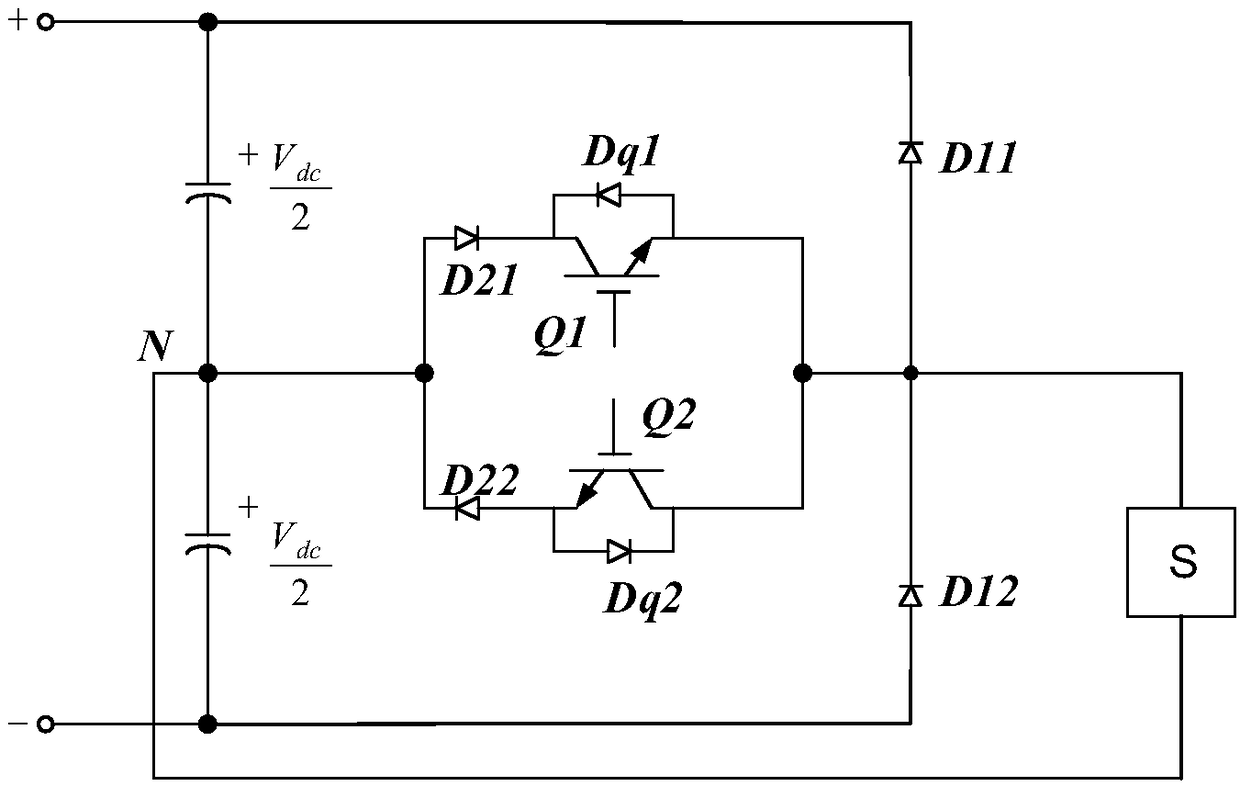
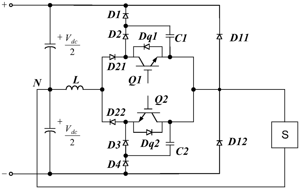
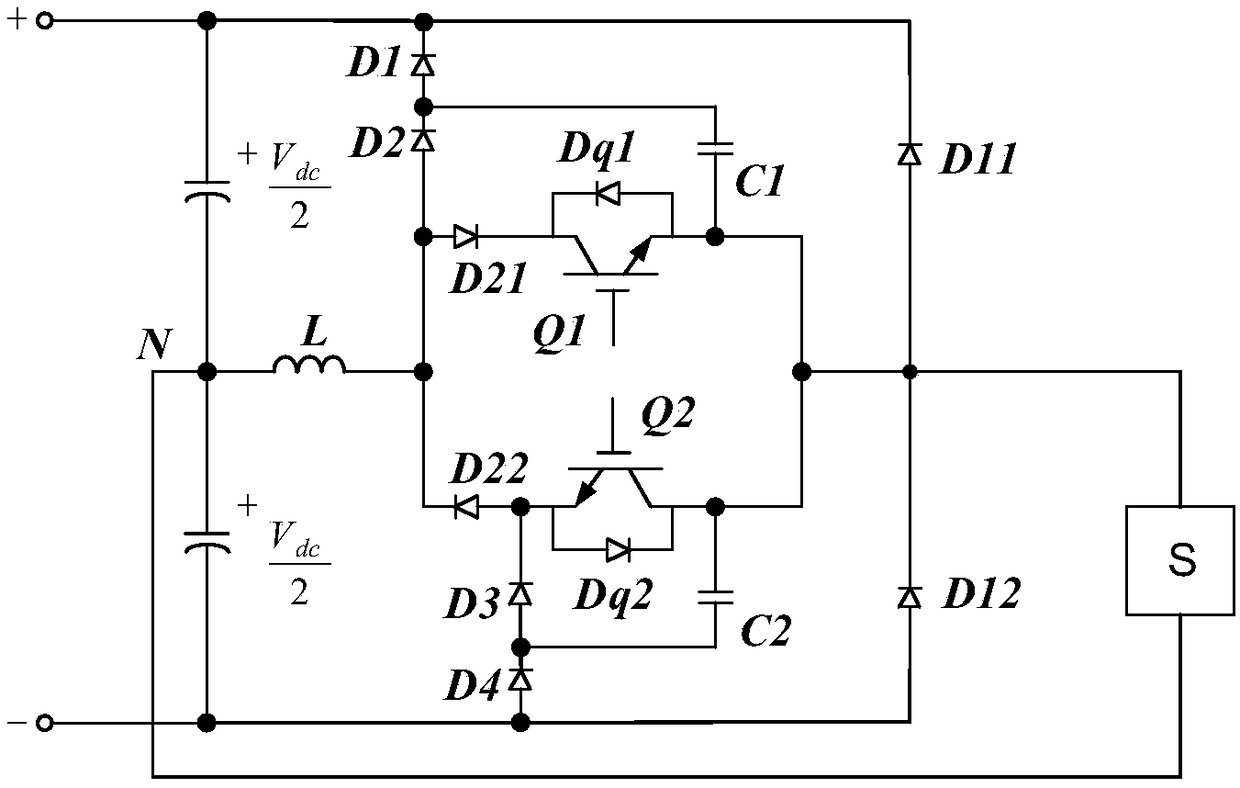
[0045] The core of the present invention is to provide a T-shaped rectifier circuit and a corresponding three-phase rectifier circuit, which uses the internal circuit topology to enable the first controllable switch and the second controllable switch to realize soft switching, thereby reducing the need for controllable switches. On-off power consumption; moreover, devices can be added without changing the internal circuit layout of the traditional T-type rectifier circuit, so that the circuit topology is compact and the busbar design is simple, which is conducive to electrical layout and structural design, and Retrofit costs are reduced.

[0046] In order to make the purpose, technical solutions and advantages of the embodiments of the present invention clearer, the technical solutions in the embodiments of the present invention will be clearly and completely described below in conjunction with the drawings in the embodiments of the present invention. Obviously, the described e...


PUM


Abstract

The invention discloses a T-shaped rectifying circuit and a corresponding three-phase rectifying circuit, By utilizing an internal circuit topology, A first controllable switch and a second controllable switch are both soft-switched. Namely, zero voltage switch, zero current switch or zero voltage zero current switch, or on-off switch with limited dv/dt and di/dt, which reduces the on-off power consumption of controllable switch, and makes the on-off power consumption of T-type rectifier circuit can be very small when the working frequency is relatively high, so that the on-off power consumption of T-type rectifier circuit is very low. In addition, the present application builds on conventional T-type rectifying circuits, Only one inductor is added, Four diodes and two capacitors do not require additional controllable switches and control circuits, and devices can be added without substantially changing the internal circuit layout of the traditional T-type rectifier circuit, so that the circuit topology structure is compact and the bus bar design is simple, thereby facilitating the electrical layout and structure design, and reducing the reconstruction cost.

Description

technical field [0001] The invention relates to the technical field of rectification, in particular to a T-shaped rectification circuit and a corresponding three-phase rectification circuit. Background technique [0002] At present, the T-type rectifier circuit has been widely used, please refer to figure 1 , figure 1 It is a structural schematic diagram of a T-shaped rectifier circuit in the prior art, which includes: two vertically arranged rectifier diodes and two horizontally arranged controllable switches; wherein, the two vertically arranged rectifier diodes The diodes are connected in series in the forward direction, the cathode of the first rectifying diode D11 is connected to the positive busbar, and the anode of the second rectifying diode D12 is connected to the negative busbar; two horizontally arranged controllable switches are each connected in series with a unidirectional diode and then connected in parallel in the middle On the bridge arm, one end of the mi...

Claims


Application Information

Patent Timeline
Patent Type & Authority Applications(China)
IPC IPC(8): H02M7/219
CPCH02M7/219H02M1/0058Y02B70/10
Inventor 陈成辉陈四雄易龙强
Owner KEHUA DATA CO LTD
Why Eureka
Try Eureka