
Single crystal material polishing device and polishing method based on inductively coupled plasma

A plasma and inductive coupling technology, applied in the direction of circuits, discharge tubes, electrical components, etc., can solve the problems of high cost, expensive refining, and affecting the accuracy of photolithography steps, and achieve the effect of small quantity and fast removal rate

Pending Publication Date: 2018-12-25
SOUTH UNIVERSITY OF SCIENCE AND TECHNOLOGY OF CHINA
View PDF7 Cites 5 Cited by
  • Summary
  • Abstract
  • Description
  • Claims
  • Application Information

AI Technical Summary

Problems solved by technology

[0006] 2. New defects such as etching pits will be introduced. Since dislocations will be generated when silicon carbide grows, and dislocations on the wafer surface have higher reactivity, they will tend to preferentially react with corrosive substances in the polishing solution. , thus leaving etching pits on the surface, these etching pits will affect the accuracy of subsequent photolithography steps, and at the same time will affect the electrical properties of the fabricated device
[0007] 3. It takes a lot of refining. In the process of chemical mechanical polishing, it is necessary to continuously add refining to the polishing pad to maintain the efficiency of grinding. Therefore, refining requires a lot of money, and some grinding processes need to use oxidation. Cerium refining is a precious rare earth material, which will also increase the cost. At the same time, extensive use of refining requires post-processing of the used refining, which is costly and pollutes the environment.
[0008] 4. The wafer after chemical mechanical polishing is stained with a large amount of abrasive slurry, and when the abrasive slurry dries on the surface of the wafer, the particles of the abrasive slurry will bond with the atoms on the surface of the wafer, so it is necessary to clean the wafer after chemical mechanical polishing. After the wafer is cleaned, surfactants are used to weaken and destroy the chemical bonds between the particles and the wafer to remove these particles, help the particles to diffuse away from the surface, and use corresponding chemical reagents to adjust the charge on the surface of the wafer and particles, Prevents it from re-precipitating, so post-wash steps also increase reagent and time costs

Method used


Image

  • Single crystal material polishing device and polishing method based on inductively coupled plasma
  • Single crystal material polishing device and polishing method based on inductively coupled plasma
  • Single crystal material polishing device and polishing method based on inductively coupled plasma

Examples


Embodiment Construction

[0034] The idea, specific structure and technical effects of the present invention will be clearly and completely described below in conjunction with the embodiments and accompanying drawings, so as to fully understand the purpose, scheme and effect of the present invention. It should be noted that, in the case of no conflict, the embodiments in the present application and the features in the embodiments can be combined with each other.

[0035] It should be noted that, unless otherwise specified, when a feature is called "fixed" or "connected" to another feature, it can be directly fixed and connected to another feature, or indirectly fixed and connected to another feature. on a feature. In addition, descriptions such as up, down, left, right, front, and back used in the present invention are only relative to the mutual positional relationship of the components of the present invention in the drawings.

[0036] Also, unless defined otherwise, all technical and scientific ter...


PUM


Abstract

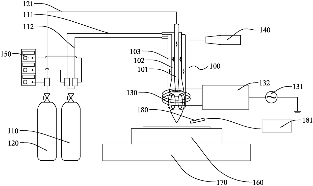
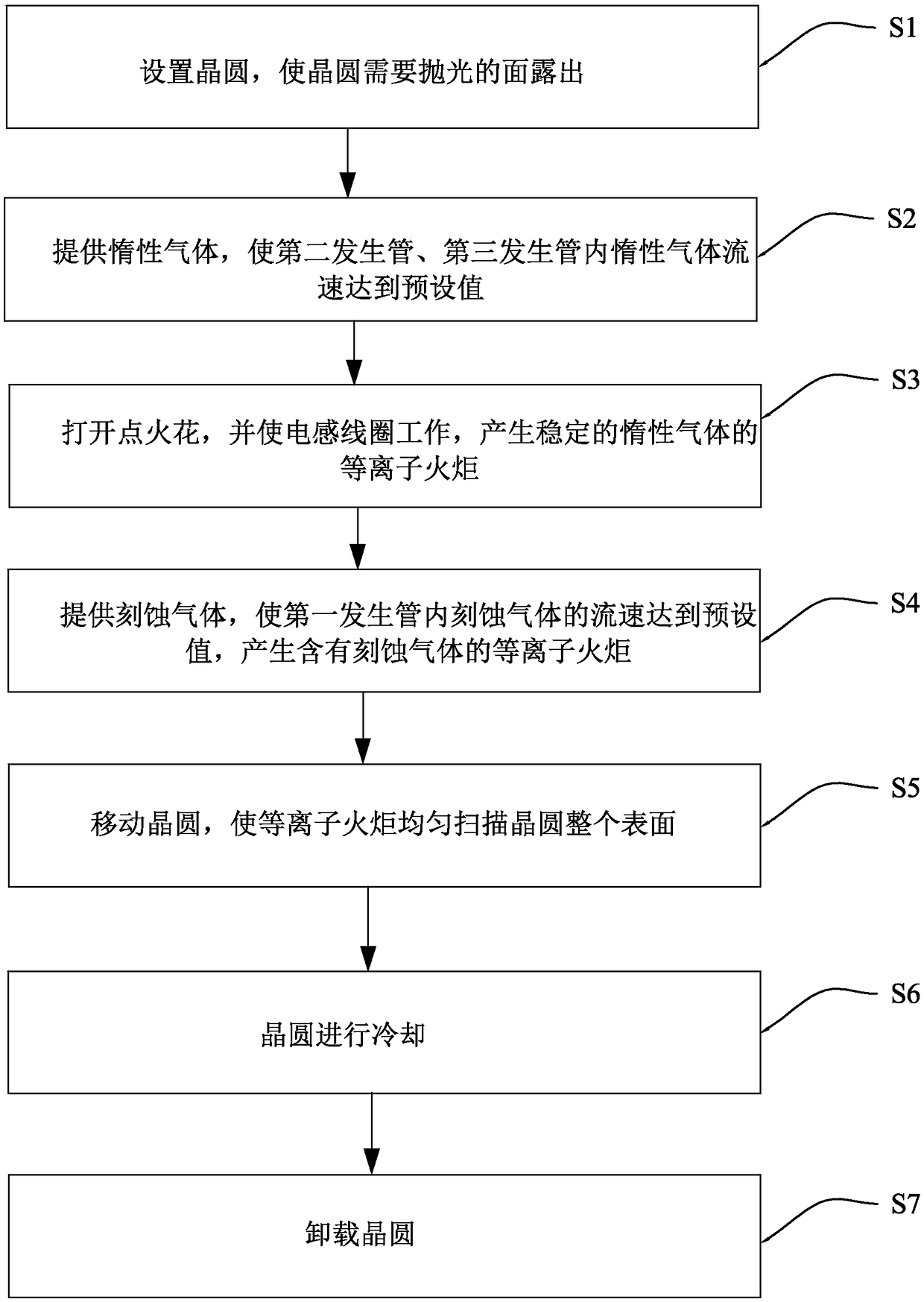
The invention relates to the technical field of single crystal material polishing, and discloses a single crystal material polishing device and polishing method based on inductively coupled plasma. The single crystal material polishing device based on inductively coupled plasma comprises: a rectangular tube, wherein the rectangular tube comprises a first generating tube, a second generating tube arranged outside the first generating tube and a third generating tube arranged outside the second generating tube; an inert gas supply device in communication with the second generation pipe and the third generation pipe; an etching gas supplying device in communication with the first gas generating tube; a spark generator in communication with the torque tube; an inductor coil, wherein an outletof a torque tube is arranged in the inductor coil and is connected with a radio frequency power supply. The single crystal material polishing method based on inductively coupled plasma of the presentinvention is based on the polishing device. The single crystal material polishing device and polishing method based on the inductively coupled plasma body of the invention have the advantages of fastremoval rate, no introduction of sub-surface damage, no need for grinding slurry and no need for post-cleaning.

Description

technical field [0001] The invention relates to the technical field of single crystal material polishing, in particular to an inductively coupled plasma-based single crystal material polishing device and polishing method. Background technique [0002] The manufacturing process of semiconductor wafers includes many processes such as single crystal growth, outer circle grinding, slicing, rounding, rough grinding, fine grinding, diamond polishing, and chemical mechanical polishing. Among them, the polishing process (including diamond polishing and chemical mechanical polishing) The purpose is to remove scratches and subsurface damage on the wafer surface after grinding, so as to obtain a perfect surface without scratches and damage, and then process electronic components on the surface. Since the surface quality of the polished wafer directly determines the performance of the components, polishing is a very critical step in the wafer processing process. In addition, in the manu...

Claims


Application Information

Patent Timeline
Patent Type & Authority Applications(China)
IPC IPC(8): H01J37/32
CPCH01J37/32431H01J37/32798H01J2237/3151H01J2237/02
Inventor 邓辉张翊
Owner SOUTH UNIVERSITY OF SCIENCE AND TECHNOLOGY OF CHINA
Learn More