Method for directly loading photocatalyst and filling by layers and member thereof

A photocatalyst and loading technology, applied in the field of photocatalysis, can solve the problems of small porosity of the photocatalyst layer, poor light transmittance of the photocatalyst layer, and weak loading of the photocatalyst, so as to achieve enhanced photocatalytic effect, good adsorption performance, and avoidance of falling effect

Active Publication Date: 2019-01-01
OCEAN UNIV OF CHINA
View PDF7 Cites 2 Cited by
  • Summary
  • Abstract
  • Description
  • Claims
  • Application Information

AI Technical Summary

Problems solved by technology

Although there are a variety of photocatalyst loading and loading methods, there are always various drawbacks.
For example, the widely used sol-gel method for loading photocatalysts involves first soaking the carrier in a specific catalyst precursor sol, drying and calcining at high temperature after gelling, but this method has always had the problem that the photocatalyst is not loaded firmly and the Problems such as the low activity of the fired photocatalyst
At present, the loading of most photocatalysts is that the photocatalyst is loaded on the carrier and directly loaded into the photocatalytic reactor. This kind of loading directly leads to the small porosity of the photocatalyst layer, which makes the light transmittance of the photocatalyst layer poor. cause waste of photocatalyst

Method used


Image

  • Method for directly loading photocatalyst and filling by layers and member thereof
  • Method for directly loading photocatalyst and filling by layers and member thereof
  • Method for directly loading photocatalyst and filling by layers and member thereof

Examples


Embodiment 1

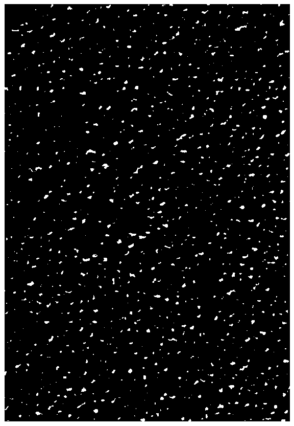
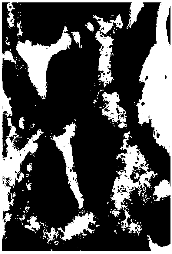
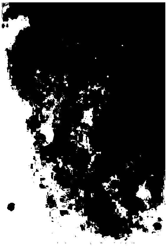
[0042] The steps of this embodiment include the preparation of the binder, the ultrasonic cleaning of the carrier, the combination of the carrier and the binder, the ultrasonic loading of the photocatalyst and the layered loading of the photocatalyst. The photocatalyst selected in this embodiment is Bi 2 WO 6 -TiO 2 Composite photocatalyst, using tetra-n-butyl titanate as titanium source, using sol-gel method and calcining at 550°C to prepare nano-powder TiO with photocatalytic activity 2 Photocatalyst, sodium tungstate and prepared nano-powder TiO with photocatalytic activity 2 As raw material, with acetone as solvent, TiO 2 The powder was added to the sodium tungstate solution and stirred, and the photocatalytically active nano-powder Bi 2 WO 6 -TiO 2 composite photocatalyst. The carrier selected in this embodiment is ceramic foam, Figure 1-3 The macroscopic topography, the 75-fold magnification and the 500-fold magnification of the foamed ceramics respectively. It c...


PUM


Abstract

The invention relates to a method for directly loading a photocatalyst and filling by layers and a member thereof. The method comprises preparation of a binding agent, ultrasonic washing of a carrier,binding of the carrier and the binding agent, ultrasonic loading of the photocatalyst and layered filling of the photocatalyst. The member comprises a metal net lining, a metal zip fastener and a plurality of layering grids, wherein the metal net lining is closed through the metal zip fastener; the metal zip fastener is connected onto the metal net lining through a metal wire which is slightly thinner than the metal net lining; one point of each layering grid is fixed on the metal net lining and then the layering grid is fixed on the metal net lining through the metal zip fastener. When the photocatalyst is loaded, high-temperature calcination is not needed; the viscosity of the binding agent is prevented from being damaged and a condition that the activity of the photocatalyst is reducedwhen the firing temperature is not proper is also avoided; the problem that the catalyst falls off, caused by subsequent high-temperature calcination, is also avoided; meanwhile, the loaded catalystcan have relatively high activity, relatively high light transmittance and relatively low pressure drop.

Description

technical field [0001] The invention relates to the technical field of photocatalysis, in particular to a method in which a photocatalyst is directly loaded on a carrier and can be loaded in layers and components thereof. Background technique [0002] Since the photocatalytic technology was proposed, the research on its treatment of pollutants has followed closely, and there are more and more researches on the application of photocatalytic technology to the removal of pollutants. In 1977, Frank et al. used TiO 2 After the photocatalytic decomposition of cyanide, research on the use of photocatalytic technology for the treatment of organic pollutants has sprung up. Photocatalysts have special electronic structures, electron transfer characteristics and light absorption properties, and their excited states exist for a long time. Under light radiation, electrons in the valence band are excited and transition to the conduction band position, forming a reduction complex in the c...

Claims


Application Information

Patent Timeline
Patent Type & Authority Applications(China)
IPC IPC(8): B01J8/00B01J19/12
CPCB01J8/0015B01J19/12
Inventor 李春虎郑锐王亮王文泰冯丽娟
Owner OCEAN UNIV OF CHINA
Why Eureka
Try Eureka