Novel high-efficiency workpiece quenching furnace

A quenching furnace and high-efficiency technology, which is applied in the field of workpiece quenching furnaces, can solve the problems of scalding the operator, heavy maintenance workload, and large thermal lag, and achieve the effects of shortening the preheating time, improving production efficiency, and avoiding danger.

Inactive Publication Date: 2019-01-08
天津市宝盈金属制品有限公司
View PDF0 Cites 0 Cited by
  • Summary
  • Abstract
  • Description
  • Claims
  • Application Information

AI Technical Summary

Problems solved by technology

However, the prior art has the following problems: large environmental pollution, large heat loss, short service life and large amount of maintenance. The heating step of quenching in the prior art generally uses fuel combustion heating or resistance heating, and fuel combustion will produce a large amount of harmful gases and Fuel waste residues cause great pollution to the environment. Resistance heating is wound by resistance wire. The inner and outer sides of the ring generate heat. The heat from the inner surface (close to the barrel) is conducted to the barrel, while most of the heat from the outside is lost to the air. In the middle, it causes direct loss and waste of electric energy, and because the electric heating tube uses resistance wire to generate heat, its heating temperature is as high as 300 degrees, the thermal hysteresis is large, it is difficult to accurately control the temperature, and the resistance wire is easy to burn out due to high temperature aging
The service life of commonly used electric heating coils is about half a year. Therefore, the workload of maintenance is relatively large; the work safety cannot be guaranteed. The existing technology generally adopts heating in the heating furnace first. After the heating is completed, the heating furnace is manually opened, and then the heating The final workpiece is placed in the cooling tank, which is completely done manually, not only the workload is heavy, but it is easy to have accidents where the workpiece burns the operator

Method used


Image

  • Novel high-efficiency workpiece quenching furnace
  • Novel high-efficiency workpiece quenching furnace
  • Novel high-efficiency workpiece quenching furnace

Examples


Embodiment Construction

[0016] The following will clearly and completely describe the technical solutions in the embodiments of the present invention with reference to the accompanying drawings in the embodiments of the present invention. Obviously, the described embodiments are only some, not all, embodiments of the present invention. Based on the embodiments of the present invention, all other embodiments obtained by persons of ordinary skill in the art without making creative efforts belong to the protection scope of the present invention.

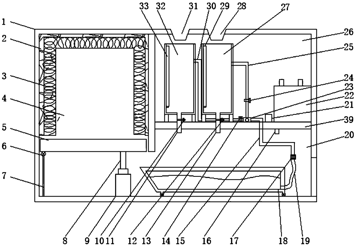
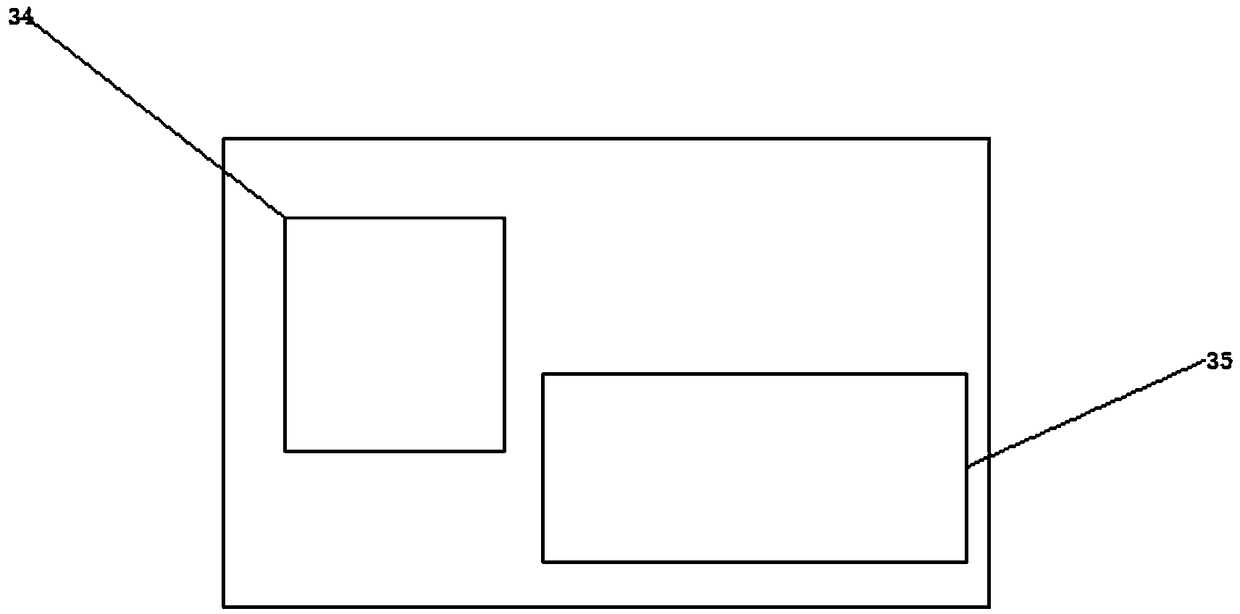
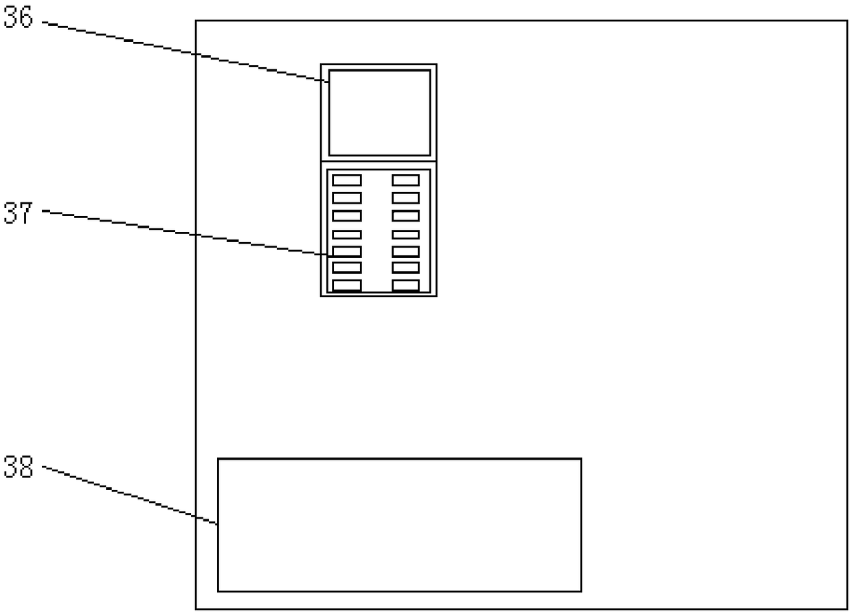
[0017] see Figure 1~4 , in the embodiment of the present invention, a novel high-efficiency workpiece quenching furnace includes a main body 1 and a heating cabin 4, the heating cabin 4 is provided with a refractory brick insulation layer 2, and the inner side of the refractory brick insulation layer 2 is provided with an electromagnetic heating coil 3, heating A bottom plate 5 is provided below the cabin 4, a roller 6 is provided at one end of the bottom pla...


PUM

PropertyMeasurementUnit
thermal efficiencyaaaaaaaaaa

Abstract

The invention discloses a novel high-efficiency workpiece quenching furnace which comprises a main body and a heating cabin, wherein a refractory brick insulation layer is arranged in the heating cabin; an electromagnetic heating coil is arranged on the inner side of the refractory brick insulation layer; a bottom plate is arranged below the heating cabin; rollers are arranged at one end of the bottom plate; supporting rods are arranged below the rollers; the other ends of the supporting rods are arranged on the lower surface inside the main body; a hydraulic cylinder is arranged on one sidesof the supporting rods; one end of the hydraulic cylinder is arranged on the lower surface inside the main body, and the other end of the hydraulic cylinder is connected with the lower surface of thebottom plate by virtue of a telescopic rod; a cooling cabin is formed in one side of the hydraulic cylinder; a cooling tank is arranged at the bottom end inside the cooling cabin; a PVC (Polyvinyl Chloride) hose is arranged at one end of the cooling tank and connected with an output pipe by virtue of a pipe connector; and an equipment cabin is formed in the upper side of the cooling cabin and partitioned from the cooling cabin by a partition plate. The novel high-efficiency workpiece quenching furnace disclosed by the invention has the characteristics of being small in environmental pollution,long in service life, maintenance-free, safe in operation and the like.

Description

technical field [0001] The invention relates to the technical field of casting quenching equipment, in particular to a novel and efficient workpiece quenching furnace. Background technique [0002] Quenching equipment refers to the equipment for solid solution treatment of materials or heat treatment process with rapid cooling process. Mainly divided into intermediate frequency quenching furnace, high frequency quenching furnace, power frequency quenching furnace, CNC quenching machine tool, integrated quenching machine tool. The quenching equipment itself is mainly composed of three parts: quenching machine tool, medium and high frequency power supply, and cooling device. The fundamental reason why quenching can strengthen steel is phase transformation, that is, austenite structure becomes martensite structure (or bainite structure) through phase transformation. Quenching can improve the hardness and wear resistance of metal workpieces, so it is widely used in various too...

Claims


Application Information

Patent Timeline
Patent Type & Authority Applications(China)
IPC IPC(8): C21D1/63C21D1/42C21D9/00
CPCC21D1/42C21D1/63C21D9/0062Y02P10/25
Inventor 郭玉宝
Owner 天津市宝盈金属制品有限公司
Why Eureka
Try Eureka