Fluorescent glass for light-emitting diodes and preparation technology thereof

A technology of light-emitting diodes and fluorescent glass, applied in the field of fluorescent glass, can solve the problems of easy stress, high sintering temperature, difficult operation in subsequent processes, etc., to avoid wear and tear and improve luminous efficiency.

Inactive Publication Date: 2019-01-15
PLATINUM OPTICS TECH SUZHOU INC +1
View PDF3 Cites 6 Cited by
  • Summary
  • Abstract
  • Description
  • Claims
  • Application Information

AI Technical Summary

Problems solved by technology

[0003] If the above-mentioned glass sheets use alkali-free glass, the alkali-free glass does not contain alkali metal oxides, but because it does not contain alkali metals and has a high content of silicon dioxide, it needs high temperature for melting, and the melting temperature is 1500 degrees Celsius. The time for maintaining this high temperature is several hours or tens of hours, so that the components of the alkali-free glass are melted and homogenized to form a molten glass, and the viscosity of the molten glass is high and the fluidity is poor, and its follow-up process is relatively difficult to operate.
In addition, the thermal expansion coefficient of this glass is about 3.0x10 -6 to 4.0x10 -6 , the thermal expansion coefficient of the phosphor is about 8.0x10 -6 , The difference in thermal expansion coefficient between glass and fluorescent powder is large. When glass and fluorescent powder are co-fired, a higher sintering temperature is required. Stress is likely to occur during such co-firing, which will also make the subsequent processing of fluorescent glass difficult.

Method used


Image

  • Fluorescent glass for light-emitting diodes and preparation technology thereof

Examples


Embodiment Construction

[0013] A number of implementations of the present application will be disclosed in the following figures. For the sake of clarity, many practical details will be described together in the following description. It should be understood, however, that these practical details should not be used to limit the application. That is to say, in some embodiments of the present application, these practical details are unnecessary. In addition, for the sake of simplifying the drawings, some well-known and commonly used structures and components will be shown in a simple schematic manner in the drawings.

[0014] The terms "first", "second", etc. used herein do not refer to the order or order, nor are they used to limit the present application, but are only used to distinguish components or operations described with the same technical terms. .

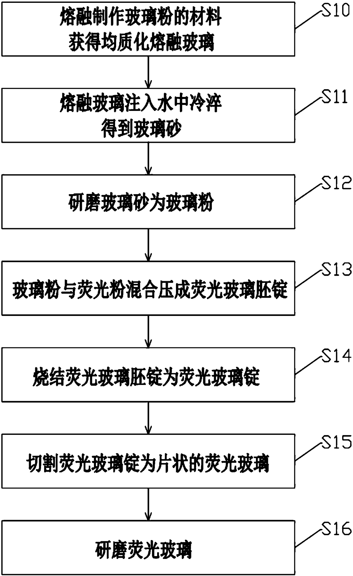
[0015] First of all, the application provides a fluorescent glass for light-emitting diodes and its preparation process. The material of the flu...


PUM

PropertyMeasurementUnit
particle diameteraaaaaaaaaa
thicknessaaaaaaaaaa
glass transition temperatureaaaaaaaaaa

Abstract

The invention relates to a fluorescent glass for light-emitting diodes and a preparation method thereof. The fluorescent glass for light-emitting diodes includes glass powder and fluorescent powder. The glass powder and fluorescent powder are mixed with to form fluorescent glass. The materials for making the glass powder include 20wt%-37wt% of silicon dioxide, 31wt%-47wt% of boron trioxide and 16wt%-35wt% of calcium oxide. The material of the fluorescent powder is selected from one of Ce-YAG, LuAG, silicate and nitride / nitrogen oxide fluorescent powder. The fluorescent glass provided by the invention is obtained by mixing and sintering of glass powder and fluorescent powder. The sintering temperature is low, and deterioration and discoloration of the fluorescent powder caused by high temperature can be avoided. Therefore, the fluorescent glass provided by the invention has good light transmittance, and the light-emitting diodes using the fluorescent glass have good luminous efficiency.

Description

technical field [0001] The invention relates to the technical field of fluorescent glass, in particular to a fluorescent glass for light-emitting diodes and a preparation process thereof. Background technique [0002] At present, white light-emitting diodes are mixed with phosphor powder and polymer silica gel and coated on the blue light chip. The phosphor powder is excited by the blue light chip to produce yellow light, and the yellow light and blue light are mixed to form white light. It is easy to produce yellowing and deterioration in the state, and then affect the luminous effect of white light emitting diodes. At present, white light-emitting diodes use fluorescent glass to solve the above problems. The fluorescent glass is coated with a phosphor layer on the surface of the glass sheet. Most of the glass sheet materials are leaded or lead-free alkali glass, such as SiO 2 -B 2 o 3 series or P 2 o 5 Add Na, K, Li and other alkali metal oxides in series. [0003] I...

Claims


Application Information

Patent Timeline
Patent Type & Authority Applications(China)
IPC IPC(8): C03C4/12C03C3/068C03C3/064C03B19/06H01L33/50
CPCC03B19/06C03C3/064C03C3/068C03C4/12H01L33/502H01L2933/0041C09K11/025C03C3/066H01L33/501Y02P40/57H01L33/507C03C14/004
Inventor 卢俊元廖翊尧林浚腾
Owner PLATINUM OPTICS TECH SUZHOU INC
Why Eureka
Try Eureka