DC/DC boost convert

A DC step-up and converter technology, which is applied in the direction of converting DC power input to DC power output, instruments, and adjusting electrical variables, can solve problems such as poor operational reliability and complicated circuit topology control methods, and achieve safety and reliability. Reduce switch electromagnetic interference, strong anti-interference effect

Active Publication Date: 2019-01-15
ZHUZHOU CSR TIMES ELECTRIC CO LTD
View PDF5 Cites 9 Cited by
  • Summary
  • Abstract
  • Description
  • Claims
  • Application Information

AI Technical Summary

Problems solved by technology

The DC / DC boost converter can realize the function of converting DC low voltage to DC high voltage. Although there are many types of current implementations of boost conversion topology circuits, there are more or less circuit topologies and / or complex control methods, poor operational reliability, etc.

Method used


Image

  • DC/DC boost convert
  • DC/DC boost convert
  • DC/DC boost convert

Examples


Embodiment Construction

[0028] In order to make the object, technical solution and advantages of the present invention clearer, the embodiments of the present invention will be further described in detail below in conjunction with the accompanying drawings.

[0029] It should be noted that the forward direction and reverse direction mentioned in the present invention are relative to the positive and negative pole voltages of the DC input power supply. The direction of the current flow is reversed.

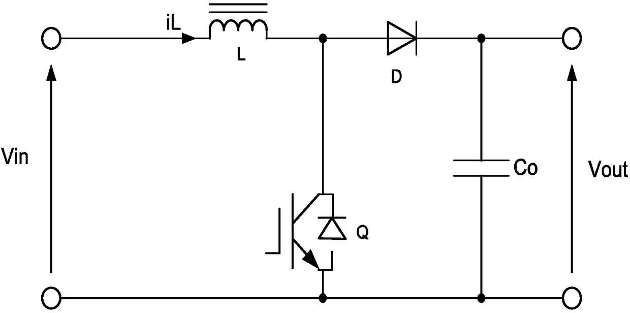
[0030] figure 1 A circuit diagram of a typical DC / DC boost converter circuit is shown. like figure 1 As shown, the circuit includes an input positive terminal, an input negative terminal, an inductor L, a power switch tube Q, a diode D, a capacitor Co, an output positive terminal, and an output negative terminal.

[0031] Wherein, one end of the inductor L is connected to the input positive terminal, and the power switch tube Q is connected between the inductor L and the input negative terminal. One e...


PUM


Abstract

A DC / DC boost convert includes an input inductor connected with a positive electrode of an input DC power supply, a step-up converter connected with that positive electrode of the step-up convert, anda step-up converter connected with the step-up converter. A main switch unit has a high-voltage end connected with an input inductance and a low-voltage end connected with a negative electrode of aninput DC power supply; A first absorption capacitor connected in parallel with the main switching unit; An auxiliary switching unit having a high-voltage terminal connected in series with a resonant inductor and connected in parallel with the first absorption capacitor; An output capacitor connected in parallel to both ends of the main switching unit through an output diode which is positively conductive, and a first diode which is positively conductive is serially connected to the first absorbing capacitor. The invention provides a DC / DC boost converter, which not only can normally exert thevoltage rise suppression function of soft switching operation, but also can avoid the device burning phenomenon caused by timing disturbance caused by system disturbance and wrong operation of switching transistors and the like. In addition, the invention can minimize circuit loss, improve conversion efficiency of the converter, and reduce switching electromagnetic interference (EMI).

Description

technical field [0001] The invention relates to the field of power electronics, in particular to a DC / DC boost converter. Background technique [0002] DC / DC boost converters are widely used in switching power supply, power factor correction (PFC), new energy represented by wind power generation and photovoltaic power generation, energy storage conversion and other fields. The DC / DC boost converter can realize the function of converting low DC voltage to high DC voltage. Although there are many types of existing boost conversion topology circuits, there are more or less circuit topologies and / or complex control methods, poor operational reliability and other issues. [0003] Therefore, there is an urgent need for a DC / DC boost converter, which can improve the reliability and safety of the power conversion system while improving the conversion efficiency of the system and reducing the generation of electromagnetic interference (EMI). Contents of the invention [0004] I...

Claims


Application Information

Patent Timeline
Patent Type & Authority Applications(China)
IPC IPC(8): H02M3/155H02M1/14
CPCH02M1/14H02M3/155Y02B70/10
Inventor 陈艺峰胡家喜朱淇凉蹇芳唐海燕张洪浩赵香桂王南张蓉任艺
Owner ZHUZHOU CSR TIMES ELECTRIC CO LTD
Why Eureka
Try Eureka