
Flue gas grading waste heat recovery condensing water collection white flue gas eliminating device and work method thereof

A waste heat recovery and flue gas condensation technology, which is applied in combustion methods, greenhouse gas reduction, climate sustainability, etc., to achieve the effects of reducing investment, improving thermal efficiency, and reducing coal consumption

Pending Publication Date: 2019-01-18
HUADIAN ELECTRIC POWER SCI INST CO LTD
View PDF9 Cites 10 Cited by
  • Summary
  • Abstract
  • Description
  • Claims
  • Application Information

AI Technical Summary

Problems solved by technology

[0006] The purpose of the present invention is to overcome the disadvantages that the environmental protection transformation technology in the prior art cannot achieve simultaneous energy saving, emission reduction and white elimination, and to provide a device and a working method for flue gas classification waste heat recovery, condensation, water collection, and white elimination. Soot, SO 2 At the same time of emission, the heat recovery and utilization of high-temperature flue gas are realized, and at the same time, SO is synergistically removed 3 , to achieve the purpose of recovering flue gas moisture, saving coal and reducing consumption, and eliminating visual pollution from white smoke plumes

Method used


Image

  • Flue gas grading waste heat recovery condensing water collection white flue gas eliminating device and work method thereof
  • Flue gas grading waste heat recovery condensing water collection white flue gas eliminating device and work method thereof

Examples


Embodiment Construction

[0030] The present invention will be further described in detail below in conjunction with the accompanying drawings and examples. The following examples are explanations of the present invention and the present invention is not limited to the following examples.

[0031] Example.

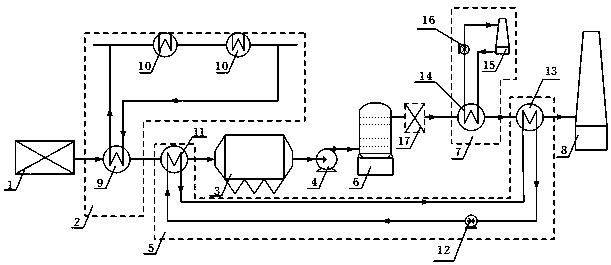
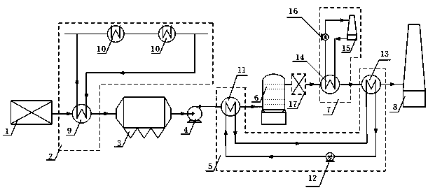
[0032] see Figure 1 to Figure 2, the flue gas classification waste heat recovery device in this embodiment condenses water collection and whitening, including an air preheater 1, a high-temperature flue gas waste heat recovery system 2, a high-efficiency dust removal system 3, an induced draft fan 4, and flue gas secondary waste heat recovery and Reheating system 5, desulfurization system 6, flue gas condensation water collection system 7 and chimney 8; air preheater 1, high temperature flue gas waste heat recovery system 2, high-efficiency dust removal system 3, induced draft fan 4, desulfurization system 6, flue gas condensation The water collection system 7 and the chimney 8 are arranged seque...


PUM


Abstract

The invention relates to a flue gas grading waste heat recovery condensing water collection white flue eliminating device and a work method thereof. In order to solve the problem in the prior art thatan existing environment protection alteration technology cannot achieve energy conservation, emission reduction and white flue gas elimination synchronously, the device is provided. The device comprises an air preheater, a high-temperature flue gas waste heat recovery system, an efficient dust removing system, an induced draft fan, a flue gas secondary waste heat recovery and reheating system, adesulfurization system, a flues gas condensing water collection system and a chimney; the air preheater, the high-temperature flue gas waste heat recovery system, the efficient dust removing system, the induced draft fan, the desulfurization system, the flues gas condensing water collection system and the chimney are successively arranged in the flowing direction of flue gas. According to the device, high-temperature flue gas heat is effectively recycled, the thermal efficiency of a boiler is improved, the coal consumption of the boiler is reduced, secondary waste heat recovery of flue gas isconducted to heat purified flue gas, therefore the visual pollution of white flue plume of the flue gas is effectively eliminated, through flue gas condensing dehydration, moisture in the flue gas isrecycled, and the purposes of water collection and white flue gas elimination are achieved.

Description

technical field [0001] The invention relates to a device and a working method for flue gas grading waste heat recovery, condensation, water collection and whitening. Background technique [0002] With the advancement of the national ultra-low emission transformation, most coal-fired power plants have adopted the "limestone-gypsum" wet desulfurization process, such as the Chinese patent application number 200910262976.5. The flue gas is changed from dry flue gas to wet flue gas. Pollutant SO 2 At the same time, a large amount of liquid water is vaporized into the flue gas. [0003] The wet flue gas discharged from the chimney is in contact with the ambient air at a lower temperature. During the cooling process of the flue gas, the water vapor contained in the flue gas is supersaturated and condensed, and the condensed water droplets refract and scatter the light, so that the smoke plume appears white. Or gray, call it "white smoke". [0004] The white smoke plume will prod...

Claims


Application Information

Patent Timeline
Patent Type & Authority Applications(China)
IPC IPC(8): F23J15/08F23J15/06F23J15/02
CPCF23J15/02F23J15/06F23J15/08F23J2215/20Y02E20/30
Inventor 杜振朱跃李壮梁秀进刘强魏宏鸽
Owner HUADIAN ELECTRIC POWER SCI INST CO LTD
Learn More