
A fault detection device for oil-immersed transformer based on micro-nano optical fiber evanescent field

A technology of oil-immersed transformers and micro-nano optical fibers, which is applied in the measurement of color/spectral characteristics, etc., can solve the problems of limited fuel cell life, high cost, and short equipment life, and achieve improved anti-vibration and noise performance and detection speed Fast, easily reusable effects

Active Publication Date: 2021-01-05
NANJING UNIV OF AERONAUTICS & ASTRONAUTICS
View PDF4 Cites 0 Cited by
  • Summary
  • Abstract
  • Description
  • Claims
  • Application Information

AI Technical Summary

Problems solved by technology

[0005] (1) The oil-gas separation detection method requires an oil-gas separation device, which makes the sensing system very complicated and greatly reduces the long-term reliability of the online monitoring device
[0006] (2) Photoacoustic spectroscopy needs to configure lasers with specific wavelengths for each fault characteristic gas dissolved in transformer oil, resulting in high cost and complicated devices, and leading the transformer oil out of the box may cause oil pollution and affect the performance of the transformer. Stable operation
[0007] (3) Fuel cell detection method, fuel cell life is limited, electrolyte is easy to leak
[0008] (4) Catalytic fuel type sensor detection method, short equipment life, serious zero drift
[0009] (5) Infrared spectrum detection technology is more accurate, but the cost is high and it is difficult to apply on a large scale

Method used


Image

  • A fault detection device for oil-immersed transformer based on micro-nano optical fiber evanescent field
  • A fault detection device for oil-immersed transformer based on micro-nano optical fiber evanescent field
  • A fault detection device for oil-immersed transformer based on micro-nano optical fiber evanescent field

Examples


Embodiment Construction

[0037] Below in conjunction with accompanying drawing, technical scheme of the present invention is described in further detail:

[0038] This invention may be embodied in many different forms and should not be construed as limited to the embodiments set forth herein. Rather, these embodiments are provided so that this disclosure will be thorough and complete, and will fully convey the scope of the invention to those skilled in the art. In the drawings, components are exaggerated for clarity.

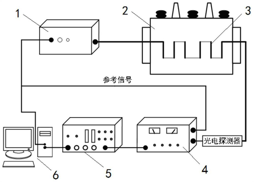
[0039] Such as figure 1 As shown, the present invention discloses an oil-immersed transformer fault detection device based on the micro-nano optical fiber evanescent field, which includes a tunable semiconductor laser light source, a segmented micro-nano optical fiber, a photoelectric detector, a lock-in amplifier, a data acquisition card and control module.

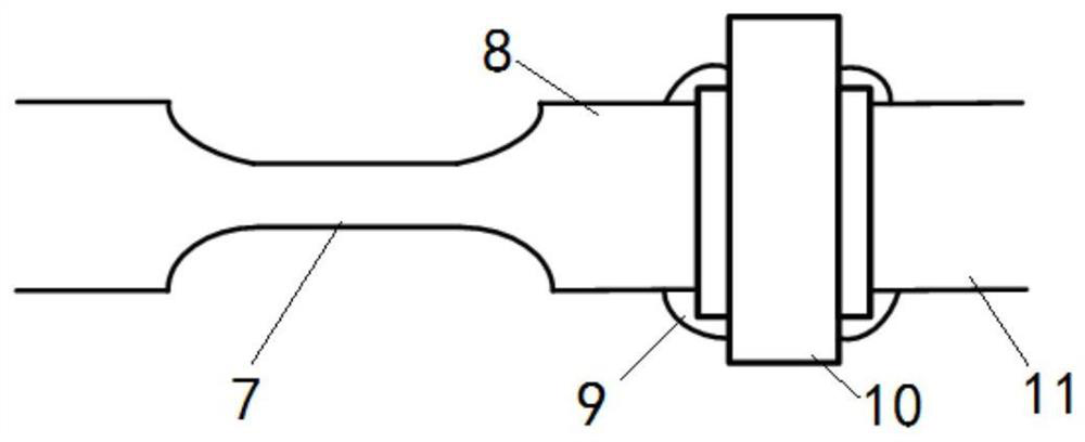
[0040] Such as figure 2 As shown, the segmented micro-nano optical fiber is set in the oil in the main box of the oil-immer...


PUM

PropertyMeasurementUnit
diameteraaaaaaaaaa

Abstract

The invention discloses an oil-immersed transformer fault detection device based on a micro-nanofiber optical fiber evanescent field. The device comprises a tunable semiconductor laser source, a sectional type micro-nanofiber, a photoelectric detector, a phase-locked amplifier, a data collection card and a control module; and the sectional type micro-nanofiber optical fiber is immersed into oil ina to-be-detected oil-immersed transformer main tank body. By judging an attenuation rate of the laser with the corresponding wavelength of each dissolving fault feature gas after the broadband laserpasses through the sectional type micro-nanofiber, whether each dissolving fault feature gas is produced in the oil of the to-be-detected oil-immersed transformer main tank body is obtained, and thenwhether the to-be-detected oil-immersed transformer is in fault or the fault type is obtained. The method disclosed by the invention has the advantages of being free from oil-gas separation, capable of simultaneously detecting multiple gases, high in sensitivity, fast in detection speed, good in repeatability and real-time in detection.

Description

technical field [0001] The invention relates to the technical field of electrical equipment fault detection, in particular to an oil-immersed transformer fault detection device based on the micro-nano optical fiber evanescent field. Background technique [0002] When an oil-immersed transformer has an electrical fault or a thermal fault, gases such as hydrogen, carbon monoxide, carbon dioxide, methane, acetylene, ethylene, and ethane will be produced. These gases will be dissolved in the transformer oil and are called fault characteristic gases. By analyzing the components of dissolved gases in transformer oil, different fault types such as local overheating, partial discharge and arc discharge can be judged. At present, the international community generally accepts the use of dissolved gas component analysis technology in transformer oil to diagnose early faults of transformers. The fault type of the transformer can be judged by the dissolved gas analysis technology in the...

Claims


Application Information

Patent Timeline
Patent Type & Authority Patents(China)
IPC IPC(8): G01N21/39
CPCG01N21/39
Inventor 江军汪卓玮张潮海王凯
Owner NANJING UNIV OF AERONAUTICS & ASTRONAUTICS
Learn More