
Test device and method of four-port sensor signal splitter with LED

A sensor signal and testing device technology, applied in the direction of measuring devices, instruments, measuring electricity, etc., can solve the problems of easy fatigue of testers, inconvenient popularization, and expensive signal harness detectors, and achieve low testing costs and high testing efficiency. Effect

Pending Publication Date: 2019-01-29
SHANGHAI UNIV OF ENG SCI
View PDF0 Cites 6 Cited by
  • Summary
  • Abstract
  • Description
  • Claims
  • Application Information

AI Technical Summary

Problems solved by technology

[0003] However, the performance test of the sensor signal splitter in this way is not only slow and inefficient, and the testers are prone to fatigue, but also easy to cause false detection or missed detection. In addition, the imported signal harness tester is expensive and not easy to popularize.

Method used


Image

  • Test device and method of four-port sensor signal splitter with LED
  • Test device and method of four-port sensor signal splitter with LED
  • Test device and method of four-port sensor signal splitter with LED

Examples


Embodiment

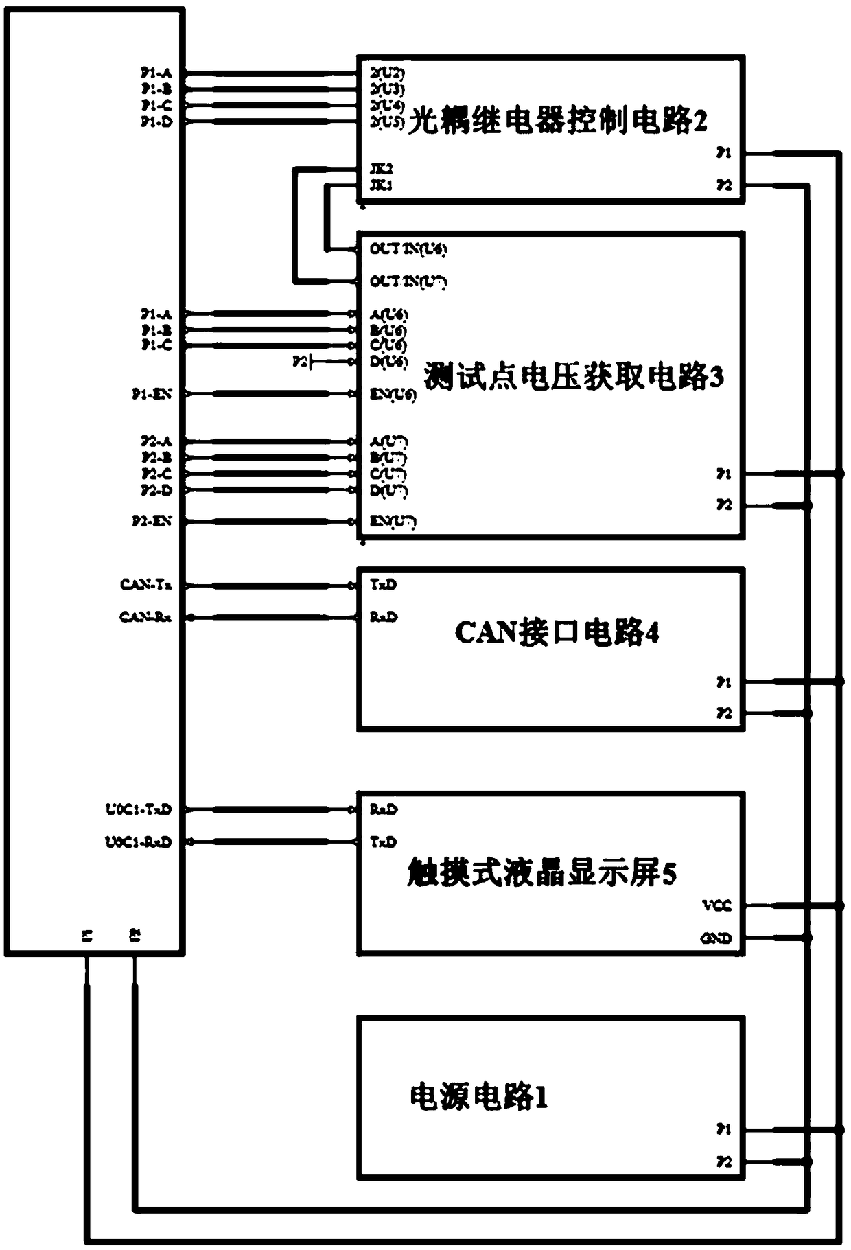
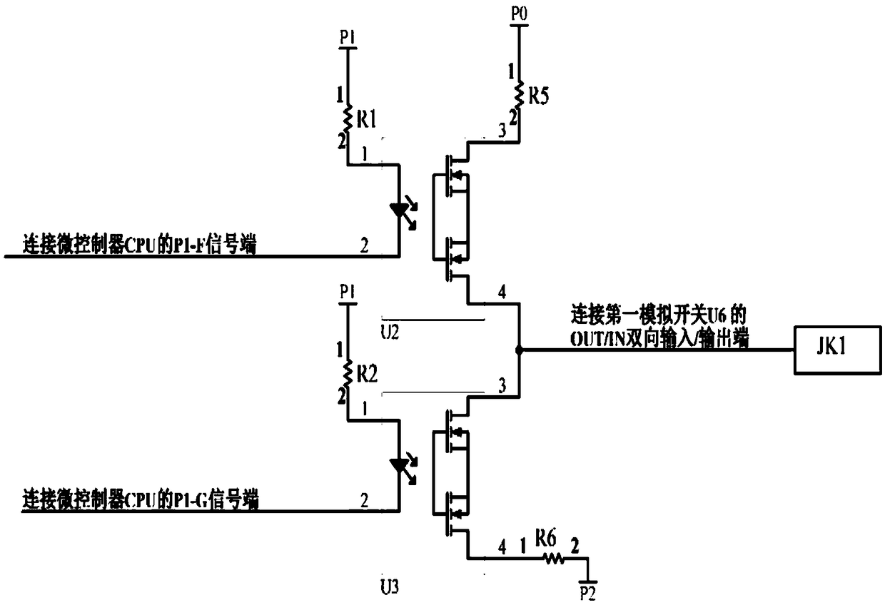
[0031] The schematic circuit diagram of the present invention is as figure 1 As shown, a test device for a four-port sensor signal splitter with LED, the device includes a power supply circuit 1, a microcontroller CPU, an optocoupler relay control circuit 2, a test point voltage acquisition circuit 3, a CAN interface circuit 4, Touch LCD screen5.

[0032] The circuit diagram of the power supply circuit 1 is shown in figure 2 As shown, the power circuit 1 includes power input socket J1, power chip U1, power input filter capacitor C1, power output filter capacitor C2, freewheeling diode D1, energy storage inductor L1, +12V power interface P0, +5V power interface P1 and PGND ground terminal P2, the power chip U1 model is MIC4680-5.0BM, its IN power input terminal is connected to the +12V power interface P0 and the V+ signal terminal of the power input socket J1, the GND power ground terminal is connected to the PGND ground terminal P2 and the power supply The V- signal termina...


PUM

PropertyMeasurementUnit
Inductance valueaaaaaaaaaa

Abstract

The invention relates to a test device and method of a four-port sensor signal splitter with an LED. The device comprises a power circuit, a microcontroller, an optical coupling relay control circuit,a test point voltage acquisition circuit, a CAN interface circuit and a touch liquid crystal display screen, wherein the microcontroller, the optical coupling relay control circuit, the test point voltage acquisition circuit, the CAN interface circuit and the touch liquid crystal display screen are connected with the power circuit, the microcontroller is connected with the optical coupling relaycontrol circuit and the test point voltage acquisition circuit by a digital output port and an analog-digital conversion interface, is connected with the CAN interface circuit by a CAN interface and is connected with the touch liquid crystal display screen by a universal series interface, five test socket of the test point voltage acquisition circuit are respectively connected with a bus plug, a first port plug, a second port plug, a third port plug and a fourth port plug of the four-port sensor signal splitter with the LED. The device has the advantages of low test cost, high test efficiencyand the like and is convenient to use.

Description

technical field [0001] The invention relates to the field of signal wiring harness production and maintenance, in particular to a testing device and method for a four-port sensor signal splitter with LEDs. Background technique [0002] The prior art uses a multimeter, a buzzer or an indicator light to manually overlap point by point, and observe whether there is an electric, sound or light signal to judge the on-off of each connecting line and the LED of the four-port sensor signal splitter with LED. A performance test that indicates a failure. [0003] However, the performance test of the sensor signal splitter in this way is not only slow and inefficient, and the testers are prone to fatigue, but also easy to cause false detection or missed detection. In addition, the imported signal harness tester is expensive and not easy to popularize. Contents of the invention [0004] The object of the present invention is to provide a test device and method for a four-port sensor ...

Claims


Application Information

Patent Timeline
IPC IPC(8): G01R31/02G01R35/02
CPCG01R35/02G01R31/50
Inventor 周建鹏龚元明吴长水
Owner SHANGHAI UNIV OF ENG SCI
Learn More