A temperature field regulation mechanism that facilitates the control of directional solidification and flat liquid-solid interface

A liquid-solid interface, directional solidification technology, applied in the field of photovoltaics, can solve the problems of solidified melt vibration, central supercooling, adverse effects of crystal growth, etc., to improve heat transfer efficiency, ensure overall quality, and increase the effect of disturbance effect.

Active Publication Date: 2020-08-04
石棉达升再生资源有限公司
View PDF3 Cites 0 Cited by
  • Summary
  • Abstract
  • Description
  • Claims
  • Application Information

AI Technical Summary

Problems solved by technology

[0005] The technical problem to be solved by the present invention is: in the existing operation process of using the cooling plate alone to cool the bottom of the crucible for directional solidification or combined with moving the solidified melt downwards out of the induction area, so as to obtain a unidirectional temperature gradient, there is a central overshoot. Insufficiencies such as cold or solidified melt vibrations have adverse effects on crystal growth. The present invention provides a temperature field regulation mechanism that solves the above problems and is beneficial to control the directional solidification and flat liquid-solid interface.

Method used


Image

  • A temperature field regulation mechanism that facilitates the control of directional solidification and flat liquid-solid interface
  • A temperature field regulation mechanism that facilitates the control of directional solidification and flat liquid-solid interface
  • A temperature field regulation mechanism that facilitates the control of directional solidification and flat liquid-solid interface

Examples


Embodiment 1

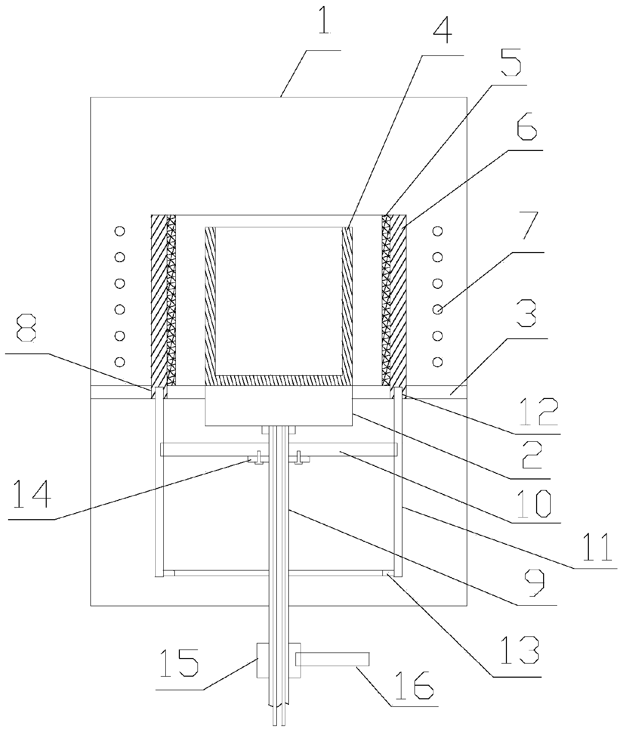
[0041] This embodiment provides a temperature field control mechanism that is beneficial to control the directional solidification and flat liquid-solid interface, including a furnace body 1, a cooling plate 2 with a coaxial center line is provided in the furnace body 1, and a There is a heat insulation ring plate 3, the radial outer edge of the heat insulation ring plate 3 is in contact with the inner wall of the furnace body 1, and the radial inner edge is in contact with the outer wall of the cooling plate 2; the crucible 4 is placed on the upper plate of the cooling plate 2, and the crucible 4. The outer jacket is provided with a thermal insulation tube 6, the inner wall of the thermal insulation tube 6 is fixed with a graphite heating element 5, and the outer ring of the thermal insulation tube 6 is provided with an electromagnetic induction coil 7;

[0042] There is also a ring groove 8 on the heat insulation ring plate 3, the axial bottom end of the insulation tube 6 fit...

Embodiment 2

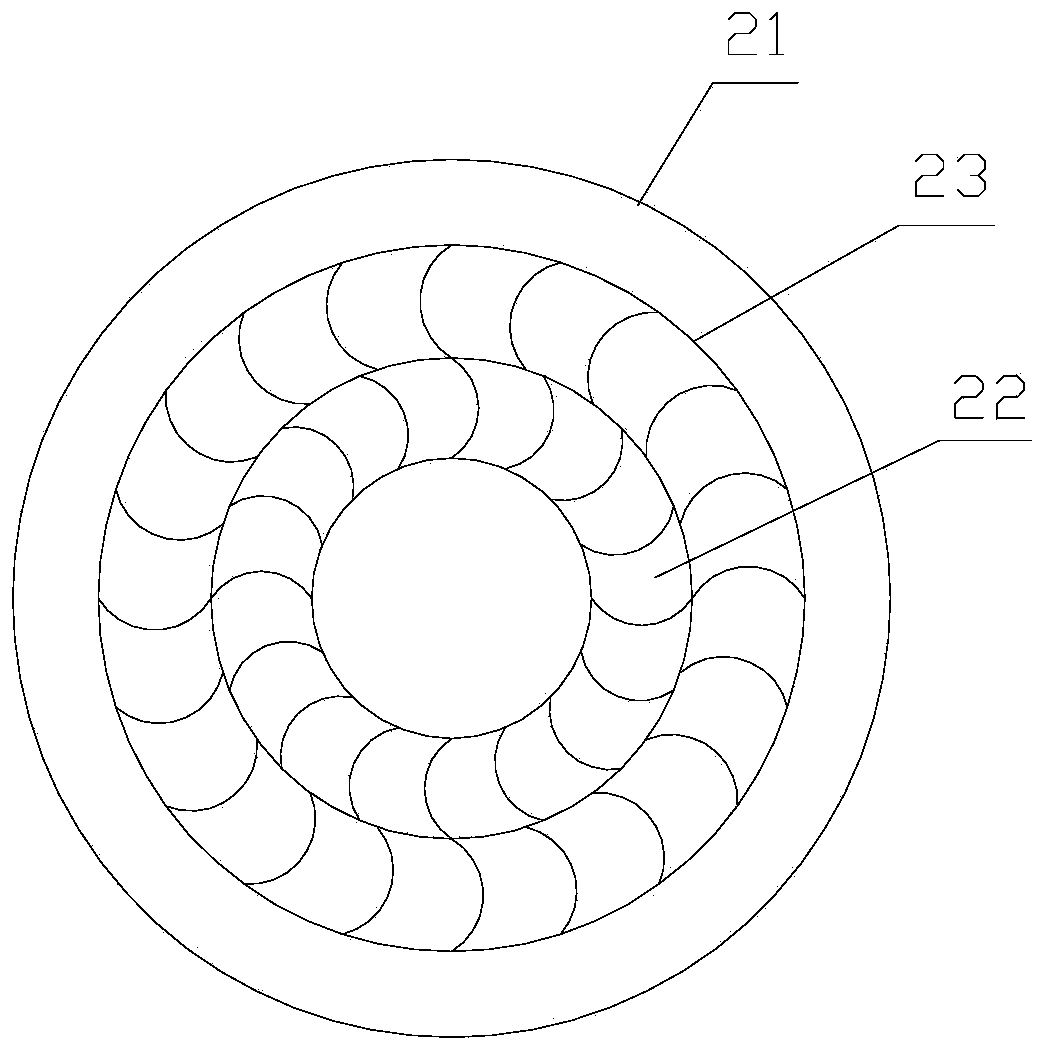
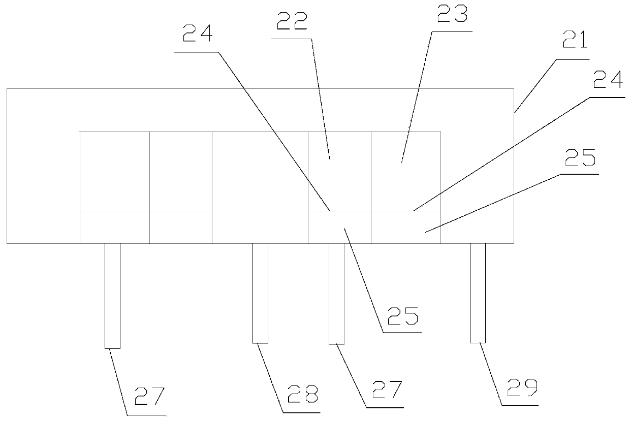
[0045] Further improvement on the basis of Embodiment 1, the fins 26 on the first annular gas distribution chamber 22 and the second annular gas distribution chamber 23 are distributed at equal intervals along the circumference, and the gas output end of each fin 26 The direction of the board surface is arranged obliquely, and the inclination angle relative to the bottom surface of the housing 21 is 60-80°. The fins 26 in the first annular gas distribution chamber 22 are all inclined clockwise, and the fins 26 in the second annular gas distribution chamber 23 are all inclined counterclockwise. The pressure difference between the gas pressure passing into the first annular gas distribution chamber 22 and the gas passing into the second annular gas distribution chamber 23 is 0.05-0.15 MPa.

Embodiment 3

[0047] Further improvement on the basis of Example 2, the lifting mechanism includes a rotating sleeve 9, a driven disc 10 and a driving mechanism; the furnace body 1 below the heat insulating ring plate 3 extends into the rotating sleeve 9, and the rotating One axial end of the sleeve 9 is driven to rotate by the driving mechanism, and the other axial end is rotationally connected with the lower plate surface of the cooling plate 2; An adjustment cylinder 11 is threadedly connected to the edge, and the axial upper end of the adjustment cylinder 11 is connected to the heat preservation cylinder 6 by being embedded in the limit card slot 12; , drive the adjusting cylinder 11 to move up and down through screw transmission, thereby pushing the heat preservation cylinder 6 and the graphite heating element 5 to move up or down. The air intake pipe 27 , the first exhaust pipe 28 and the second exhaust pipe 29 all pass through the rotating sleeve 9 and protrude to the external enviro...


PUM


Abstract

The invention discloses a thermal field regulating controlling mechanism beneficial for controlling of directional solidification flat straight liquid solid interfaces. According to the thermal fieldregulating controlling mechanism beneficial for controlling of directional solidification flat straight liquid solid interfaces, in a furnace body, the outer rim of a thermal insulation circular plateis contacted and connected with the internal wall of the furnace body, and the inner rim is contacted with the external wall of a cooling disk; a crucible is placed on the upper plate surface of thecooling disk; the crucible is sleeved with a thermal insulation barrel, a graphite heating body, and an electromagnetic coil; a cooling circular plate is provided with a circular groove; the axial bottom end of the thermal insulation barrel is designed to penetrate through the circular groove; the lower part of a thermal insulation circular plate is provided with an adjusting barrel; the upper endof the adjusting barrel is connected with the thermal insulation barrel; an adjusting barrel is driven by an elevating mechanism to move upward and downward; the cooling disk comprises a cylindricalhousing; a first circular gas distribution chamber and a second circular gas distribution chamber which are sleeved with each other are arranged in the cylindrical housing; separating plates are arranged in the two distribution chambers; the part below each separating plate is designed to be a buffer chamber, and the part above each separating plate is provided with a plurality of gas distributionfins; the bottom of each buffer chamber is communicated with a gas inlet pipe; and the bottom of the housing is provided with a gas outlet pipe. The thermal field regulating controlling mechanism isbenefit for solving of a problem that center supercooling degree is too large, unfavorable influences on solidification melt such as vibration are avoided, it is beneficial for polysilicon growth; energy is saved, and environmental protection is realized.

Description

technical field [0001] The invention relates to the field of photovoltaic technology, in particular to a temperature field regulation mechanism that is beneficial for controlling directional solidification and flat liquid-solid interface. Background technique [0002] At present, the development and utilization of solar energy is mainly in the form of solar cells. Solar cells are devices that directly convert light energy into electrical energy through the photoelectric effect. Silicon is known for its high abundance, high voltage resistance, high temperature resistance, and large crystal band width Compared with other semiconductor materials, it has comprehensive advantages such as small size, high efficiency, long life, strong reliability, stable performance and non-toxicity, mature preparation technology and wide range of uses, so it has become the main material of solar cell research, development, production and application. Crystalline silicon cells have become the lead...

Claims


Application Information

Patent Timeline
Patent Type & Authority Patents(China)
IPC IPC(8): C30B11/00C30B29/06C30B28/06
CPCC30B11/003C30B11/006C30B28/06C30B29/06
Inventor 羊实庹开正
Owner 石棉达升再生资源有限公司
Why Eureka
Try Eureka