Curing device and method for internal cooling and humidification of mass concrete

A large-volume concrete and concrete technology, which is applied in the processing of building materials, construction, building construction, etc., can solve the problems of concrete humidification and maintenance, achieve good maintenance effect, improve utilization rate, and improve humidification efficiency

Active Publication Date: 2019-02-22
CHANGJIANG RIVER SCI RES INST CHANGJIANG WATER RESOURCES COMMISSION
View PDF8 Cites 18 Cited by
  • Summary
  • Abstract
  • Description
  • Claims
  • Application Information

AI Technical Summary

Problems solved by technology

A humidification mechanism is installed in it, but since there are no ventilation holes inside the conveying pipeline, the humidification mechanism cannot perform humidification and maintenance on the inside of the concrete.

Method used


Image

  • Curing device and method for internal cooling and humidification of mass concrete
  • Curing device and method for internal cooling and humidification of mass concrete
  • Curing device and method for internal cooling and humidification of mass concrete

Examples


Embodiment 1

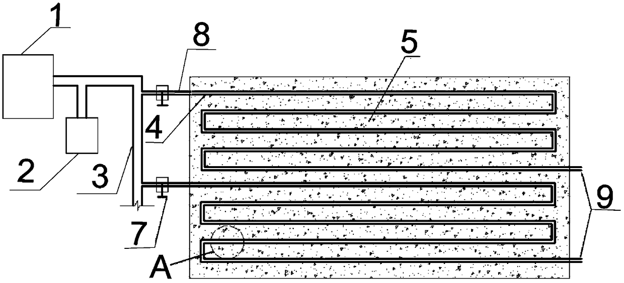
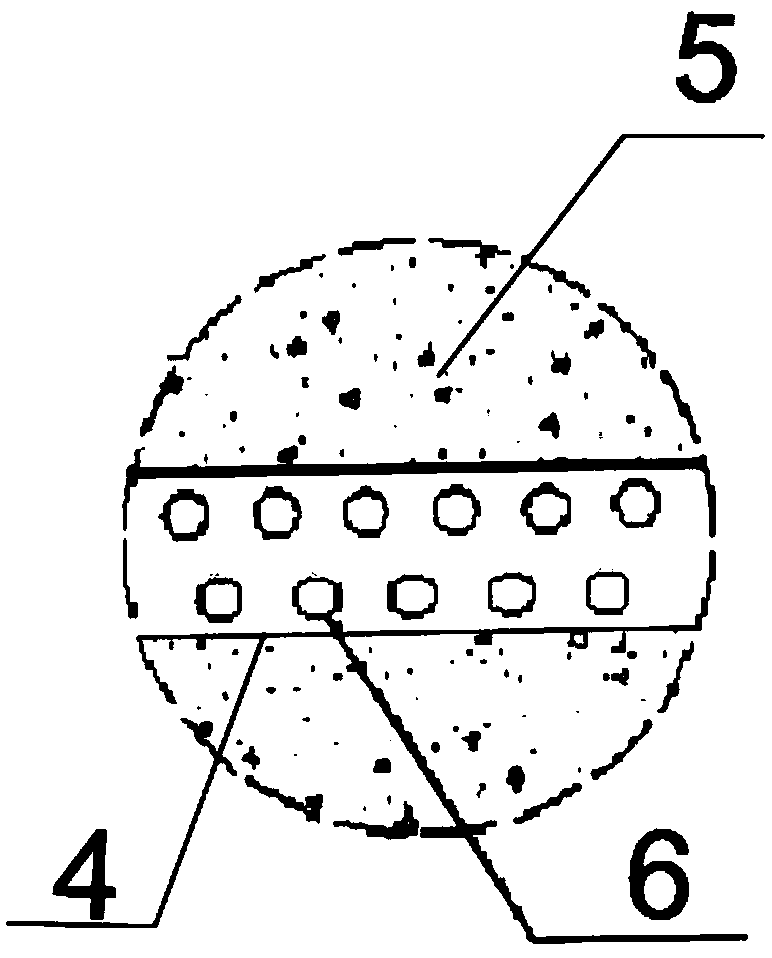
[0038] Such as Figure 1-2 As shown, a maintenance device for mass concrete internal cooling and humidification in this embodiment includes an air refrigerator 1, an atomizer 2 and a cold air pipeline; the cold air pipeline includes a main cold air pipeline 3 and a plurality of uniformly pre-buried in The cold air buried pipe 4 in the concrete 5, the air outlet of the air refrigerator 1 and the mist exhaust port of the atomizer 2 are connected with the cold air main pipe 3, and the cold air main pipe 3 is connected to multiple cold air buried pipes 4 at the same time, and the cold air buried pipe inlet 8 A control valve 7 is set; a plurality of ventilation holes 6 are set on the pipe wall of the cold air buried pipe 4 . The cold air buried pipe outlet 9 is located outside the concrete. The nebulizer adopts a high-power ultrasonic nebulizer. Refrigeration equipment adopts industrial air conditioners, and its power is customized according to the construction progress. The wet...

Embodiment 2

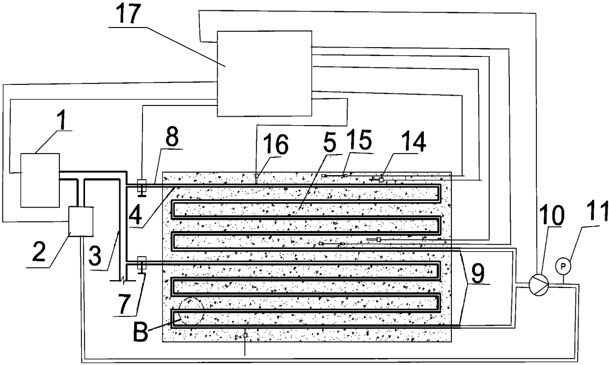
[0041] Such as Figure 3-4 As shown, compared with Embodiment 1, the cold gas buried pipe outlet 9 of this embodiment is connected to a vacuum pipeline, and a vacuum pump 10 and an electronic vacuum gauge 11 are arranged on the vacuum pipeline. The outlet of the vacuum pump 10 is connected to the air inlet of the atomizer 2 . The inner wall of the buried cold air pipe 4 is provided with a breathable anti-blocking retaining ring 12 . A plurality of moisturizing rings 13 are arranged in the inner wall of the cold air buried pipe 4, and the plurality of moisturizing rings 13 are evenly arranged along the length direction of the cold air buried pipe; A plurality of temperature sensors and humidity sensors are fixedly arranged on the periphery of the concrete 5 and on the internal steel bars. The temperature and humidity sensor is an integrated probe type temperature and humidity sensor 14 . A plurality of stress sensors 15 are fixedly arranged on the outer and inner steel bars ...


PUM


Abstract

The invention relates to a curing device and method for internal cooling and humidification of mass concrete. The curing device comprises an air refrigerating machine, an atomizer and a cold air pipeline; the cold air pipeline comprises a cold air main pipeline and a plurality of roundabout cold air buried pipes evenly pre-buried in the concrete; an air outlet of the air refrigerating machine anda mist exhaust opening of the atomizer are connected with the cold air main pipeline, the cold air main pipeline is simultaneously connected with the multiple cold air buried pipes, and control valvesare arranged at inlets of the cold air buried pipes; and a plurality of vent holes are formed in the pipe walls of the cold air buried pipes. The curing device adopts low-temperature atomized water vapor instead of refrigerated water as a refrigerant, thus the double effects of internal cooling and wet curing are achieved, drying shrinkage and temperature shrinkage can be reduced simultaneously,and crack resistance is effectively realized; large-scale engineering facilities for storage of cooling water are not needed on site; refrigerating air preparation is high in efficiency and low in cost; the pipe burst risk is avoided in the period of construction cooling; and after the cooling period is finished after concrete setting, water can be directly poured into a cooling pipe, and wet curing is further continued through water seepage.

Description

technical field [0001] The invention belongs to the field of construction, and in particular relates to a maintenance device and method for cooling and humidifying the interior of large-volume concrete. Background technique [0002] Today, cracks are still a persistent problem plaguing mass concrete structures. Research and practice have shown that temperature stress is the most important cause of mass concrete cracking during construction and even operation. During the construction period, the hydration reaction of the cementitious material in the concrete will generate a large amount of heat, which will cause the temperature of the structure to rise, and the internal and external temperature difference deformation caused by the temperature rise will easily cause cracks on the surface of the structure under the action of self-constraint. The temperature stress generated by the overall cooling temperature difference in the later period under the action of external constrain...

Claims


Application Information

Patent Timeline
Patent Type & Authority Applications(China)
IPC IPC(8): E04G21/02
CPCE04G21/02
Inventor 李家正李明霞林育强颉志强周世华石妍陈霞闫小虎杨梦卉张建峰
Owner CHANGJIANG RIVER SCI RES INST CHANGJIANG WATER RESOURCES COMMISSION
Why Eureka
Try Eureka