
Terahertz biosensing device

A biosensor and terahertz technology, which is applied in the field of terahertz time-domain spectroscopy, can solve the problems of not easy portability, leakage of terahertz waves, large samples, etc., and achieve the effect of convenient detection and saving of usage.

Pending Publication Date: 2019-02-22
CAPITAL NORMAL UNIVERSITY
View PDF0 Cites 14 Cited by
  • Summary
  • Abstract
  • Description
  • Claims
  • Application Information

AI Technical Summary

Problems solved by technology

However, it has the following limitations: (1) The sample is too large; since the spot size of the terahertz focus is determined by the diffraction limit, samples smaller than the wavelength will make the terahertz wave leak
(2) The spectral resolution is low; due to the terahertz reflector, detector and coherent components in the optical path, the detected terahertz pulse will have a reflected echo, and the reflected echo is generated after the main wave. During Fourier transform, the distance between the main wave and the reflected echo limits the length of the time window, which affects the spectral resolution after Fourier transform, making the sample absorption peak that should appear difficult to be found
(3) The system size is large; the main components of a typical terahertz time-domain spectroscopy system include the following parts, a femtosecond laser with a wavelength of 800nm, a terahertz transmitting and receiving part, and a collimating and focusing optical path, which makes it difficult to reduce the size of the system. Can't be portable
(4) Absorption of water: Due to the influence of hydrogen bonds in water, water absorbs terahertz strongly, and the system requires that the sample volume should not be too small, which causes great difficulties in the extraction of terahertz spectra from water-soluble biological samples
The problem with this method is that the terahertz time-domain spectroscopy system is too large and not easy to carry, and the loss of terahertz propagation in space is relatively large

Method used


Image

  • Terahertz biosensing device
  • Terahertz biosensing device
  • Terahertz biosensing device

Examples


Embodiment Construction

[0021] The present invention will be described in detail below with reference to the accompanying drawings and examples.

[0022] Terahertz waveguides can be divided into two categories. The first category is free-space waveguides, which trap and confine terahertz radiation generated in free space, with prominent examples being suspended-line waveguides and parallel-plate waveguides. The second category is on-chip waveguides, where the THz radiation is confined near the surface, such as coplanar lines, microstrip lines, or coplanar waveguides. Compared to free-space waveguides, on-chip waveguides typically exhibit higher attenuation and dispersion because the propagating electric field is mostly confined to the lossy dielectric material compared to free-space. They are therefore generally not suitable for transmitting signals over long distances, but waveguides can be made more compact by photolithography and can provide high-frequency resolution for spectroscopic application...


PUM

PropertyMeasurementUnit
Thicknessaaaaaaaaaa
Lengthaaaaaaaaaa
Widthaaaaaaaaaa

Abstract

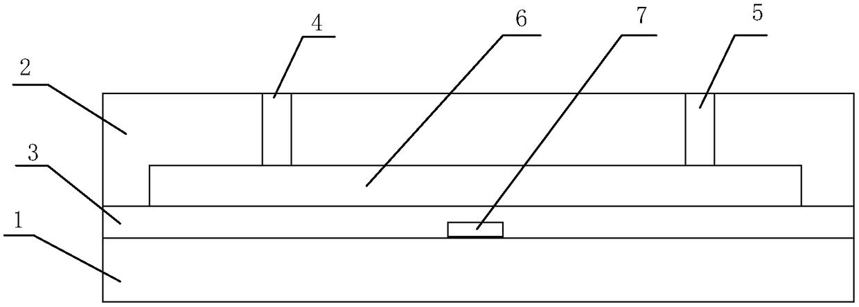
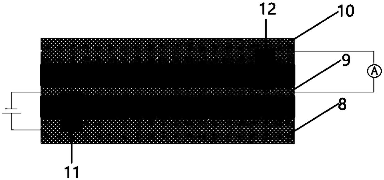
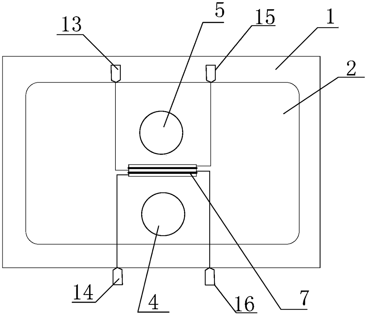
The invention discloses a terahertz biosensing device. Coplanar waveguide and microfluidic channel are designed on a device, generation, transmission and detection of terahertz and a microfluidic chipare integrated together, a terahertz signal is directly generated under excitation of external pump laser, and terahertz detection on a liquid biological sample in the microfluidic channel of the device can be achieved; application of a terahertz TDS system is prevented, and detection on a biological sample is facilitated; and the channel shape and thickness size of the terahertz microfluidic chip based on coplanar waveguide is designed according to the factors of fluid mechanics, various biomolecular dimensions, terahertz detection regional radius and the like, and is suitable for terahertzspectrum detection of most biological solution samples; and furthermore, the usage of samples can be saved since the small channel size of the microfluidic chip.

Description

technical field [0001] The invention belongs to the technical field of terahertz time-domain spectrum measurement of liquid samples, and in particular relates to a terahertz biosensor. Background technique [0002] Terahertz wave refers to electromagnetic waves with a frequency between 0.1 and 10 THz (wavelength between 30 and 3000 μm), and its wave band is between microwave and infrared. The rapid development of ultrafast laser technology and semiconductor material science and technology in the past decade has provided a stable and reliable excitation source for the generation of terahertz pulses, and promoted the wide application of terahertz in spectroscopy and imaging technology. [0003] The terahertz time-domain spectroscopy system uses femtosecond lasers to excite photoconductive materials or electro-optical materials. After the emitted terahertz pulses are focused, they are irradiated on the sample, and the terahertz pulses are modulated by the sample. The terahertz ...

Claims


Application Information

Patent Timeline
IPC IPC(8): G01N21/3586G01N21/3577
CPCG01N21/3577G01N21/3586
Inventor 文毅伟苏波武亚雄赵亚平吴蕊何敬锁张盛博张存林
Owner CAPITAL NORMAL UNIVERSITY
Learn More