Ultra-wideband and high-gain fiber and device fabrication technology

A high-gain fiber, gain fiber technology, applied in laser parts, lasers, electrical components, etc., can solve problems such as uncompact structure and complex pumping mechanism, achieve high luminous efficiency, avoid excess heat, and achieve tunable lasers output effect

Active Publication Date: 2019-03-01
SOUTH CHINA UNIV OF TECH
View PDF11 Cites 9 Cited by
  • Summary
  • Abstract
  • Description
  • Claims
  • Application Information

AI Technical Summary

Problems solved by technology

[0007] The purpose of the present invention is to solve the urgent problem of realizing high-performance broadband tunable laser output in the above-mentioned prior art, expand its application in the field of broadband tunable single-frequency fiber laser and high repetition frequency mode-locked fiber laser, and provide a super Broadband High Gain Optical Fiber and Device Fabrication Technology
More preferably, the present invention also optimizes the species of rare earth ions, and co-dopes sensitized rare earth ions in different fan-shaped or annular core regions. After the sensitized rare earth ions absorb the pump light of a single wavelength, the energy will be effectively transferred to the Different rare earth luminescent ions, so as to solve the problems of complex pumping mechanism and non-compact structure in the prior art

Method used


Image

  • Ultra-wideband and high-gain fiber and device fabrication technology
  • Ultra-wideband and high-gain fiber and device fabrication technology
  • Ultra-wideband and high-gain fiber and device fabrication technology

Examples


Embodiment 1

[0040] In this embodiment, an ultra-broadband high-gain optical fiber and device preparation technology includes the following steps:

[0041] (1) Preparation of gain fiber:

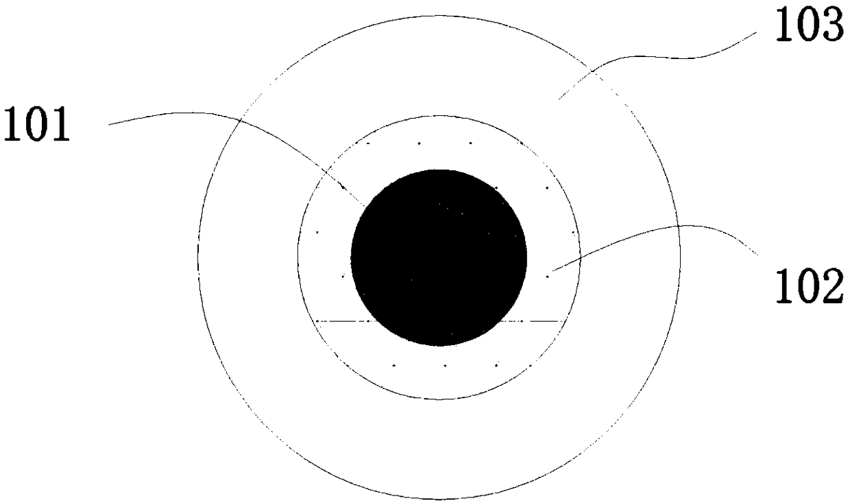
[0042] End face such as figure 1 As shown, the gain fiber is a fiber with a composite structure, including a core and a cladding 103 covering the surface of the core. The fiber core is composed of two rare earth ion doped regions 101 and 102 arranged in concentric circles. Wherein the rare earth ion doped region 101 is Er 3+ / Yb 3+ Doped multi-component silicate glass, the rare earth ion doped region 102 is Tm 3+ / Yb 3+ Doped multi-component germanate glass, the cladding layer 103 is multi-component germanate glass not doped with rare earth; Er 3+ 、Tm 3+ , Yb 3+ The doping concentrations are all >5wt%.

[0043] The gain fiber is prepared by a core melting drawing method, and the steps are as follows:

[0044] a. Glass melting: use the traditional melting-annealing method to melt Er respectively...

Embodiment 2

[0052] In this embodiment, an ultra-broadband high-gain optical fiber and device preparation technology includes the following steps:

[0053] (1) Preparation of gain fiber:

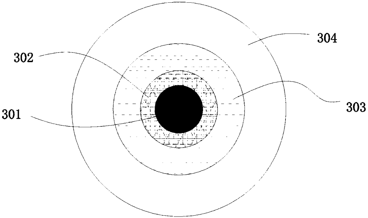
[0054] End face such as image 3 As shown, the gain fiber includes a core and a cladding 304 covering the surface of the core. The fiber core is composed of three rare earth ion doped regions 301 , 302 and 303 arranged in concentric circles. Wherein the rare earth ion doped region 301 is Er 3+ / Yb 3+ Doped multi-component germanate glass, the rare earth ion doped region 302 is Tm 3+ / Yb 3+ Doped multi-component germanate glass, the rare earth ion doped region 303 is Ho 3+ / Yb 3+ Doped multi-component germanate glass, the cladding layer 304 is multi-component germanate glass not doped with rare earth. Among them Er 3+ 、Tm 3+ 、Ho 3+ and Yb 3+ The doping concentrations are all >5wt%.

[0055] The gain fiber is prepared by the tube-and-rod method, and the steps are as follows:

[0056] a. Glass...

Embodiment 3

[0064] In this embodiment, an ultra-broadband high-gain optical fiber and device preparation technology includes the following steps:

[0065] (1) Preparation of gain fiber:

[0066] End face such as Figure 4 As shown, the gain fiber includes a core and a cladding 403 covering the surface of the core. The fiber core is composed of two rare earth ion doped regions 401 and 402 arranged in a symmetrical sector. Wherein the rare earth ion doped region 401 is Er 3+ / Yb 3+ Doped multi-component tellurite glass, the rare earth ion doped region 402 is Tm 3 + / Yb 3+ Doped multi-component tellurite glass, the cladding 403 is multi-component tellurite glass not doped with rare earth; Er 3+ 、Tm 3+ , Yb 3+ The doping concentrations are all >5wt%.

[0067] The gain fiber is prepared by the tube-and-rod method, and the steps are as follows:

[0068] a. Glass melting: use the traditional melting-annealing method to melt Er respectively 3+ / Yb 3+ and Tm 3+ / Yb 3+ Doped bulk cor...


PUM

PropertyMeasurementUnit
Gain coefficientaaaaaaaaaa

Abstract

The invention relates to an ultra-wideband and high-gain fiber and device fabrication technology. The fabrication technology comprises the steps of (1) fabricating a gain fiber, wherein the gain fiberis a composite structure fiber, a fiber core is multiple groups of symmetrically-distributed fan-shaped structures or a plurality of concentric circular structures and comprises at least two different types of rare earth-doping glass, and a light-emitting center is arranged at different fan-shaped structure or circular structure regions in the fiber core; and (2) building a fiber laser, wherein the gain fiber is used, rare-earth ions in different regions in the fiber core are selectively simulated by controlling shapes of pumping light spots, and tunable laser output is achieved by combiningfiber grating. The design of the fiber structure and optical field distribution control of pumping light are combined, the fabricated gain fiber has the characteristics of high gain and ultra wideband, remaining heat generated by all-fiber core pumping is prevented by selectively simulating the light-emitting ions in a special region, and the fabrication technology can be used for a wideband-tunable single-frequency fiber laser and a high-repetition frequency locked-mode fiber laser.

Description

technical field [0001] The invention relates to the technical field of optical fibers and optical fiber lasers, in particular to an ultra-broadband high-gain optical fiber and device preparation technology. Background technique [0002] A fiber laser usually consists of a pump source, a gain fiber, and a resonant cavity. The gain fiber is usually a rare-earth-doped glass fiber, which is the core of the fiber laser; the pump source provides energy to make the rare-earth ions in the gain fiber generate spontaneous emission and stimulated emission; the resonator realizes the round-trip oscillation of the signal light, and finally realizes the laser output. Compared with gas lasers and traditional solid-state lasers, fiber lasers are composed of gain fibers and fiber devices (such as fiber gratings, fiber couplers, and fiber polarization controllers, etc.) , high stability, and easy adjustment of the output wavelength, it has been widely used in military and civilian fields suc...

Claims


Application Information

Patent Timeline
Patent Type & Authority Applications(China)
IPC IPC(8): H01S3/067H01S3/0941H01S3/10
CPCH01S3/06716H01S3/0941H01S3/1022H01S3/0675H01S3/06733H01S3/094007H01S3/1055H01S3/08045H01S3/1618H01S3/1608H01S3/1616H01S3/161H01S3/094053H01S3/09403H01S3/094003H01S3/094042H01S3/094065
Inventor 杨中民唐国武张智深
Owner SOUTH CHINA UNIV OF TECH
Why Eureka
Try Eureka