
Deep chamber roof deformation monitoring method integrated with detection, ranging and imaging

A roof and deep technology, which is applied in the field of roof deformation monitoring of deep chambers integrated with detection, ranging and imaging, can solve the problem of not considering the influence of errors, not being able to collect rock formation image information, and not being able to use rock formation deformation and rock formation separation information problems such as measurement, to achieve the effect of reliable equipment performance, high data accuracy, and high data accuracy

Inactive Publication Date: 2019-03-08
ZHEJIANG UNIVERSITY OF SCIENCE AND TECHNOLOGY
View PDF9 Cites 2 Cited by
  • Summary
  • Abstract
  • Description
  • Claims
  • Application Information

AI Technical Summary

Problems solved by technology

At present, the monitoring of surrounding rock deformation on the roof and floor of deep chambers mainly adopts pure mechanical roadway roof separation indicator, sound and light alarm roadway roof separation indicator, sub-station type roof separation automatic monitoring and alarm device, and displacement and pressure monitoring. etc., but these existing devices cannot simultaneously measure the settlement deformation of the deep chamber roof and the heave of the bottom plate, and cannot realize the simultaneous acquisition of deformation image information in the monitoring area, and do not involve the consideration of the thickness of the rock layer separation layer on the deep chamber. Influence of Errors on Deformation Variables of Roof and Floor
[0003] Chinese patent CN 103344495 A Rigid bearing plate center hole method servo control deep rock deformation test device and method, including load control device, force transmission device, surface and deep deformation measurement device, mainly used for pressure level deep rock deformation measurement Indoor test, it cannot be used in deep caverns to measure the deformation of the roof and floor, the information of rock formation separation and the collection of image information
[0004] Chinese patent CN 104373154 A is a method for monitoring the stability of the roof of a roadway, which includes setting a mine pressure monitoring station at the advancing position of the roadway to monitor the roadway when the roadway advances a distance, and the monitoring content of the mine pressure monitoring station includes mine pressure. pressure monitoring, drilling detection and acoustic emission observation, the invention sets up a mine pressure monitoring station to monitor the roadway, and analyzes according to the monitoring content of the mine pressure monitoring station, so as to realize the prediction and alarm of the stability of the roadway top, but it cannot be used In order to monitor the settlement deformation value and uplift value of the roof rock layer and floor rock layer of the chamber, the deformation image cannot be collected synchronously for the monitoring area
[0005] Chinese patent CN206531493U is a mining roadway roof displacement monitoring device, which includes a roadway roof displacement monitoring bolt body, a bolt tray, a nut, a high-sensitivity spring, and a pressure sensing element. The spring transmits the deformation pressure generated by the subsidence to the pressure sensing element, thereby calculating the sinking displacement of the roof of the roadway, but this device cannot be used to monitor the settlement of the roof rock layer and the heaving of the floor rock layer at the same time, nor can the roof and floor To detect the delamination information of the rock strata, it is not possible to collect image information of the rock strata in the monitoring area
[0006] Chinese patent CN 207923105 U is a subsidence displacement monitoring device for the roof of an underground space. The upper end is fixed with a partition, which solves the problem of the traditional pole-column roof subsidence detector. The pole-column roof subsidence detector is supported between the goaf roof and the floor, and the displacement sensor located on the pole column is used to detect its deformation. However, the device cannot be used for deformation monitoring of deep chamber floor and floor, deformation image information collection and separation layer information detection
[0007] Chinese patent CN 207797940 U is a measuring device for monitoring the displacement of the coal mine roadway roof, including an L-shaped pointer and a scale plate. The base on the protective cover is fixedly connected to the first mounting base by screws, and the right end of the protective cover is connected to the L-shaped plate by screws. The fixed boss at the right end of the pointer is fixedly connected, the fixed seat is fixedly connected with the top of the support frame by screws, and the mounting plate is fixedly connected with the bottom end of the support frame by screws, but it cannot be used for simultaneous monitoring of the deformation of the top and bottom plates of deep chambers and image information collection, nor can it be used to detect the separation information of the roof and bottom plates

Method used


Image

  • Deep chamber roof deformation monitoring method integrated with detection, ranging and imaging
  • Deep chamber roof deformation monitoring method integrated with detection, ranging and imaging
  • Deep chamber roof deformation monitoring method integrated with detection, ranging and imaging

Examples


Embodiment Construction

[0057] The present invention will be further described below in conjunction with the embodiments shown in the accompanying drawings.

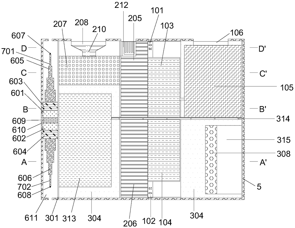
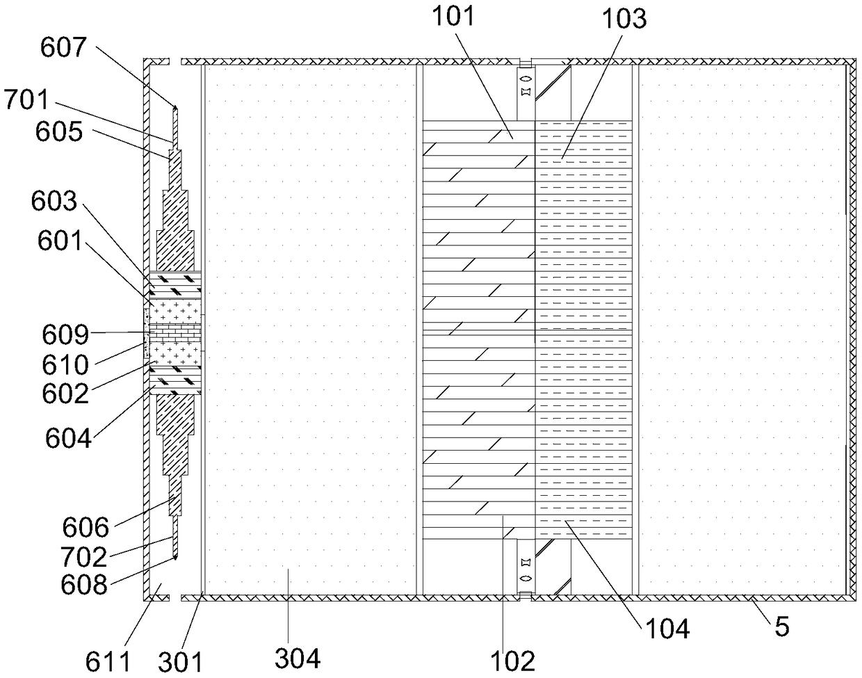
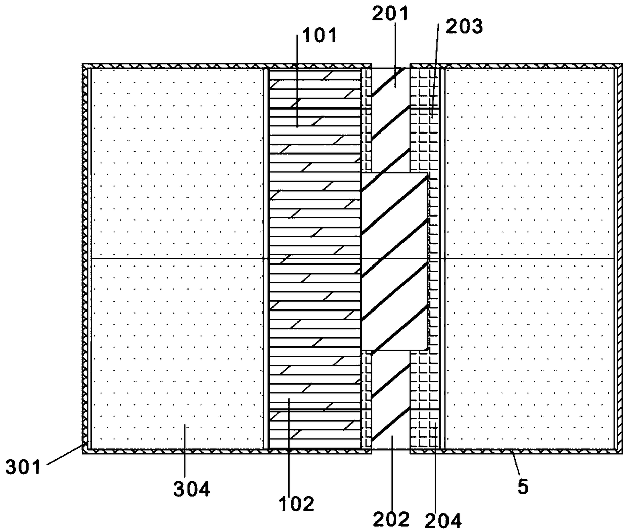
[0058] The invention provides a method for monitoring the deformation of the roof of a deep chamber with integrated detection, ranging and imaging, including:

[0059] (1) When monitoring the deformation and ranging of the roof and bottom of the deep chamber:

[0060] (1.1) Input the formation elevation to be measured through the deformation control panel 107 and transmit it to the ranging processor 105, and input the laser emission instruction through the deformation control panel 107, so that the upper laser 101 and the lower laser 102 emit laser light 110;

[0061] (1.2) The laser light emitted by the upper laser 101 reaches the roof rock layer 401 and then emits. The reflected laser light received by the upper reflection laser receiver 108 is transmitted to the upper detector 103. The laser light emitted by the lower laser device 102 is ref...


PUM


Abstract

The invention belongs to the technical field of surrounding rock deformation monitoring and deep underground engineering disaster prevention and reduction in deep underground engineering, particularlyto a deep chamber roof deformation monitoring method integrated with detection, ranging and imaging. The method adopts the upper and lower layered lasers to emit laser to collect the settlement deformation of the deep chamber roof and the uplift of the bottom plate so as to achieve the synchronous collection of deformation data of the top plate and the bottom plate, the data accuracy is high, theequipment performance is reliable, and the cost is low; upper and lower dual-layer focusing mini-type lenses are employed to collect the deformation areas of the image information of the top plate and the bottom plate of the deep chamber to achieve the synchronous collection of the image information of the deformation areas of the top plate and the bottom plate of the deep chamber and regeneratethe deformation amount of the top plate and the bottom plate of the deep chamber, the data accuracy is high, and the device performance is reliable; and upper and lower dual-layer depth detection heads stretch into the separation layers of the top plate and the bottom plate to achieve the real-time collection of the information of the separation layers of the deformation area of the top plate andthe bottom plate of the deep chamber to accurately obtain thickness information of the separation layers and ensure the reliability of the stability assessment of the top plate and the bottom plate ofthe deep chamber.

Description

technical field [0001] The invention belongs to the technical field of deformation monitoring of surrounding rocks in deep underground engineering and disaster prevention and reduction in deep underground engineering, and in particular relates to a method for monitoring deformation of a deep chamber roof with integrated detection, ranging and imaging. Background technique [0002] The deep chamber is the inevitable product of the development of mining engineering, tunnel engineering, energy storage and nuclear waste treatment projects to the deep. After entering the deep excavation, the geomechanical environment of the deep part is obviously different from that of the shallow part. The main performance is that it has "three highs" (ground stress, temperature, seepage pressure) and "one disturbance" (mining disturbance), the resulting nonlinear mechanical problems are very serious, which brings great difficulties to the deformation control of surrounding rocks such as the roof...

Claims


Application Information

Patent Timeline
Patent Type & Authority Applications(China)
IPC IPC(8): G01B11/16
CPCG01B11/16
Inventor 邹宝平高福洲罗战友陈永国杨建辉
Owner ZHEJIANG UNIVERSITY OF SCIENCE AND TECHNOLOGY
Learn More