Spatial coherent X-ray source of surface-transmitting array structure

An array structure and X-ray technology, which is applied in the field of X-ray interference imaging, can solve problems such as difficult application, affecting emission efficiency, and small X-ray divergence angle, so as to increase the range of emission angles, improve imaging quality, and improve utilization efficiency. Effect

Pending Publication Date: 2019-03-15
SHENZHEN UNIV
View PDF7 Cites 8 Cited by
  • Summary
  • Abstract
  • Description
  • Claims
  • Application Information

AI Technical Summary

Problems solved by technology

Due to the limitation of the exit window, most of the X-rays reflected from the surface of the anode target are intercepted, and only a small part is radiated from the window. The radiated X-rays have a small divergence angle, resulting in a limited imaging field of view; The array X-ray source is extended and distributed in the direction of the optical axis, so that the distance from each line emitter in the array X-ray source to the detection surface is not equal, which is not conducive to the extraction of imaging information by the plane detector, and also limits the system's Field of view
Especially in ordinary laboratories and hospitals, large field of view imaging is usually required. Since the imaging field of view of this array X-ray source is limited, it is difficult to apply it in large field of view X-ray differential imaging
[0008] Second, in terms of light extraction characteristics, the above-mentioned anode light extraction efficiency is low
In order to facilitate heat dissipation, reflective targets are usually made thicker and made on very thick copper electrodes. Most of the X-rays generated by electronic targeting are absorbed by the target and heat-dissipating electrodes, and only the X-rays generated by a very thin layer on the surface can Radiate from the target surface; and due to the limitation of the reflective structure, only the X-rays radiated at a certain angle will radiate from the window, and the X-rays emitted at most angles will be intercepted and cannot be effectively used, which is serious. Limits the utilization efficiency of X-rays
[0009] Third, due to the use of the spiral filament structure of the traditional X-ray tube, electrons are easily suppressed by space charges and filament field distribution during emission, which affects their emission efficiency; and due to the spiral structure of the filament, the emitted electron bundles diverge Larger angle affects the control of the subsequent focusing electric field on the morphology of the electron focal spot, thereby affecting the uniformity of electron distribution on the focal plane
[0010] In summary, the existing reflective X-ray sources do not meet the requirements of imaging systems for high-throughput, large field of view, and high-quality images of X-ray sources.

Method used


Image

  • Spatial coherent X-ray source of surface-transmitting array structure
  • Spatial coherent X-ray source of surface-transmitting array structure
  • Spatial coherent X-ray source of surface-transmitting array structure

Examples


Embodiment 1

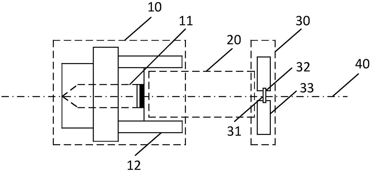
[0057] see figure 1 , is a structural schematic diagram of a spatially coherent X-ray source with a surface-emitting transmission array structure provided in this embodiment. The spatially coherent X-ray source includes a cathode 10, an electron beam converging device 20, and a transmission anode target 30. The cathode 10 includes A planar emission type electron emitter 11, wherein the planar emission type electron emitter 11, the electron beam converging device 20 and the transmissive anode target 30 are sequentially arranged on the same optical path and have a common optical axis 40;

[0058] The plane emission type electron emitter 11 has an emission plane perpendicular to the optical axis 40 for emitting the first electron beam;

[0059] The electron beam converging device 20 is used to receive and converge the first electron beam emitted by the emission plane to obtain a second electron beam, and emit the second electron beam to the transmission anode target 30 to bombard...

Embodiment 2

[0090] A schematic structural diagram of a spatially coherent X-ray source provided in this embodiment. Wherein, the spatially coherent X-ray source is optimized by the spatially coherent X-ray source described in Embodiment 1, wherein,

[0091] The electron beam converging device 20 included in the spatially coherent X-ray source is a non-imaging electron optical focusing device;

[0092] The non-imaging electron optical focusing device is used to focus the electron beam emitted by the plane-emitting electron emitter through the spontaneously generated high-voltage electric field;

[0093] The transmissive anode target is set on the focal plane of the non-imaging electron optical focusing device

[0094] As an optional embodiment, the transmissive anode target 30 includes a heat dissipation electrode 33 for heat dissipation, a microstructure target 31 for determining the X-ray focal spot structure and beam spot size, and a substrate 32 for carrying the microstructure target ...

Embodiment 3

[0113] A schematic structural diagram of a spatially coherent X-ray source provided in this embodiment. Wherein, the spatially coherent X-ray source is optimized by the spatially coherent X-ray source described in Embodiment 1, wherein,

[0114] The electron beam converging device 20 included in the spatially coherent X-ray source is an electron optical imaging device;

[0115] The electron optical imaging device is used to focus the electron beam emitted by the plane-emitting electron emitter 11 so that the electron beam is focused to generate an image, and the shape of the image is the same as the internal structure of the plane-emitting electron emitter 11;

[0116] The transmissive anode target 30 is disposed on the image plane of the electron optical imaging device.

[0117] As an optional embodiment, the planar emission type electron emitter 11 has a two-dimensional dot array microstructure, an annular zone microstructure or a one-dimensional line array microstructure, ...


PUM


Abstract

The invention provides a spatial coherent X-ray source, and the X-ray source comprises a cathode, an electron beam gathering device and a transmitting anode target. The cathode comprises a surface-transmitting type electron emitter, and the surface-transmitting type electron emitter, the electron beam gathering device and the transmitting anode target are sequentially disposed on a coaxial opticalpath. The surface-transmitting type electron emitter has a transmitting plane which is perpendicular to the optical axis and used for transmitting a first electron beam. The electron beam gathering device is used for receiving and gathering the first electron beam emitted by the transmitting plane to obtain a second electron beam, and transmitting the second electron beam to the transmitting anode target to bombard the transmitting anode target. The transmitting anode target is opposite to the cathode, and is used for generating X-rays under the bombardment of the second electron beam, and enabling the X-rays to pass through the transmitting anode target. According to the invention, the X-ray source can meet the requirements of the high throughput, large view field and high-quality imageobtaining of the X-ray source in an X-ray interference imaging system.

Description

technical field [0001] The invention relates to the field of X-ray interference imaging, in particular to a space-coherent X-ray source with a surface emission transmission array structure. Background technique [0002] X-ray grating interference imaging technology is a hotspot in the current research of X-ray phase contrast imaging technology. X-ray grating interference imaging technology was proposed by German scientist Dr. F.Pfeiffer in 2006. It uses source grating plus ordinary X-ray tube to obtain a coherent X-ray source, which makes X-ray phase contrast imaging research get rid of the need for synchrotron radiation. The dependence of the light source makes it possible for the X-ray grating phase contrast imaging technology to be realized in ordinary laboratories and hospitals. [0003] However, the method of utilizing the source grating proposed by F.Pfeiffer makes the effective field of view of the X-ray imaging system limited by the viewing angle of the X-ray tube b...

Claims


Application Information

Patent Timeline
Patent Type & Authority Applications(China)
IPC IPC(8): H01J35/02H01J35/14
CPCH01J35/02H01J35/14
Inventor 宗方轲郭金川杨君文明宋韩冬
Owner SHENZHEN UNIV
Why Eureka
Try Eureka