Process device and process method of liquid phase reaction desulfurization of sulfur dioxide and hydrogen sulfide

A technology for sulfur dioxide and process equipment, which is applied in chemical instruments and methods, separation methods, and sulfur preparation/purification, etc., can solve the problems of increased operating costs of the equipment and the inability of the purity of sulfur products to meet market demand, etc., to prevent deposition and scaling, Increase the dissolution rate and reaction rate, the effect of easy reaction

Active Publication Date: 2019-03-29
CHINA PETROLEUM & CHEM CORP +1
View PDF19 Cites 1 Cited by
  • Summary
  • Abstract
  • Description
  • Claims
  • Application Information

AI Technical Summary

Problems solved by technology

[0015] In the above disclosed patents, H 2 S and SO 2 The pressure, temperature and pH value required for the reaction in pure water are very harsh. The reaction in an organic solvent or aqueous solution requires the addition of a buffer solution or catalyst to keep the organic solvent or aqueous solution acidic. The stronger the acidity (the lower the pH value) ) is more conducive to the reaction. During the operation of the device, the buffer solution or catalyst needs to be regularly replenished to maintain the acidic conditions required for the reaction, so the operating cost of the device increases; because the obtained liquid phase sulfur solution contains buffer solution or catalyst, the sulfur product The purity cannot meet the market demand, so sulfur refining equipment is needed to improve the purity of sulfur products

Method used


Image

  • Process device and process method of liquid phase reaction desulfurization of sulfur dioxide and hydrogen sulfide

Examples


Embodiment 1

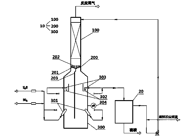
[0056] Sulfur dioxide and hydrogen sulfide liquid phase reaction desulfurization process equipment, such as figure 1 As shown, it includes a reactor 10 and a separator 20, and the reactor 10 is followed by a tail gas absorption zone 100, a liquid holding tank area 200 and a reaction zone 300 from top to bottom; the liquid holding tank area 200 includes a partition 201, Several lifters 202 and downcomers 203, the partitions 201 are fixed on the wall to isolate the tail gas absorption zone 200 from the reaction zone 300, the lifters 202 run through the partitions 201, and communicate with the tail gas absorption zone 100 and the reaction zone 300; one end of the downcomer 203 is fixed to the partition plate 201 and communicates with the tail gas absorption zone 100, and the other end extends downward to the bottom of the reaction zone 300; two nozzles 301 are arranged in the lower part of the reaction zone 300, symmetrically distributed, as The air inlet, the nozzle 301 is obliq...

Embodiment 2

[0059] use figure 1 The process device for sulfur dioxide and hydrogen sulfide reactive desulfurization process is as follows:

[0060] Pure SO 2 The gas is passed into the reaction zone 300 of the reactor 10 through two nozzles 301. The reaction solution in the reaction zone 300 is an aqueous solution of an organic basic compound. Pure H 2 S gas, the liquid in the reaction zone 300 quickly turns yellow, and it can be seen that the two react immediately to generate sulfur; the sulfur slurry flows upward into the liquid collection tank 302 under the impetus of the continuously fed gas, and is drawn out when the liquid level is higher than the liquid phase. At the outlet of the pipe 303, the sulfur-entrained slurry flows into the separator 20, the sulfur is separated from the reaction solution, and fresh reaction solution is added to the separated reaction solution, and after being pressurized by a pump, it is sent to the top of the tail gas absorption zone 100, and the reacti...

Embodiment 3

[0064] use figure 1 The process method for reactive desulfurization of sulfur dioxide and hydrogen sulfide in the shown device:

[0065] Except that the organic alkaline compound aqueous solution is 20% benzylamine solution, other conditions are the same as embodiment 2.

[0066] Access to H 2 The reaction response time of the two gases after S is 5s, calculated according to the material balance, H 2 The conversion rate of S was 93.7%.


PUM


Abstract

Disclosed are a process device and a process method of liquid phase reaction desulfurization of sulfur dioxide and hydrogen sulfide. The process device includes a reactor and a separator. The reactorincludes a tail gas absorption zone, a liquid holding tank zone and a reaction zone. The liquid holding tank zone includes a separating plate, multiple gas lifting cylinders and a liquid down pipe andcommunicates with the tail gas absorption zone and the reaction zone. The lower part of the reaction zone is provided with at least two nozzles which are symmetrically distributed. The nozzles are obliquely fixed to the device wall of the reaction zone, and nozzle heads extends obliquely upward to the inside of the reaction zone. A liquid collection tank is arranged on the upper part of the reaction zone. A liquid phase extraction pipe is arranged at the bottom of the liquid collection tank and communicates the liquid collection tank and the separator. The other end of the separator is connected to the top of the tail gas absorption zone. Reaction gas is injected into the reactor through the nozzles to be violently mixing with a reaction solution in the reactor by using the process deviceof the invention, which greatly increases the dissolution rate and reaction rate of the gas in the reaction solution. The gas ejected from two symmetrical nozzles reacts in the reaction solution to generate sulfur, and the continuously injected gas pushes the reaction solution entrained with the sulfur to flow obliquely upward into the liquid collection tank. The solution in the reactor is alwaysin a flowing state so as to prevent the sulfur from depositing and scaling on the device wall and the bottom of the reactor to ensure safe, stable and long-term operation of the device.

Description

technical field [0001] The invention relates to a process device for liquid-phase reaction desulfurization of sulfur dioxide and hydrogen sulfide, and a desulfurization method using the process device, belonging to the field of industrial production or industrial waste gas purification. Background technique [0002] Due to the development of our country's economy, the demand for crude oil continues to increase, and domestic crude oil is no longer enough to meet national needs, so imported crude oil is continuously being imported into China. From January to December 2016, China imported 381.01 million tons of crude oil, an increase of 13.6% compared with the same period last year. With the increase of my country's imported crude oil year by year, the proportion of high-sulfur crude oil is increasing. For this reason, major oil refining companies have developed a series of high-sulfur crude oil processing technology. During cracking, catalytic cracking and other processing pro...

Claims


Application Information

Patent Timeline
Patent Type & Authority Applications(China)
IPC IPC(8): B01D53/78B01D53/52B01D53/50C01B17/04
CPCB01D53/504B01D53/523B01D53/78B01D2251/80B01D2258/0283C01B17/04
Inventor 李磊王海波金平齐慧敏方向晨石平利刘炬王明星
Owner CHINA PETROLEUM & CHEM CORP
Why Eureka
Try Eureka