A kind of non-catalytic reforming reactor and its technology

A technology for reforming reactors and reforming reactions, applied in chemistry/physics/physicochemistry stationary reactors, detailed information of chemistry/physics/physicochemistry reactors, chemical instruments and methods, etc., capable of solving the complex problems of injection devices Control mechanical and electronic features, increase cost, reduce production efficiency, etc., to achieve the effect of increasing complexity, reducing soot rate, and improving reforming yield

Active Publication Date: 2021-06-08
TAIYUAN UNIV OF TECH
View PDF6 Cites 0 Cited by
  • Summary
  • Abstract
  • Description
  • Claims
  • Application Information

AI Technical Summary

Problems solved by technology

But the disadvantage of its feeder is that the complex design of the injection device requires complex mechanical and electronic features for control, which undesirably increases the cost
Chinese patent 200810012601.9 discloses a method for removing tar and coke in the process of pyrolysis and gas and a method for reforming combustible gas. By using integral heat storage honeycomb ceramics as a carrier and carrying a catalyst, the conversion and reformation is carried out under the action of an oxidant. clean, but it is necessary to remove the tar and coke attached to the porous ceramic surface, which increases the cost and reduces the production efficiency

Method used


Image

  • A kind of non-catalytic reforming reactor and its technology
  • A kind of non-catalytic reforming reactor and its technology
  • A kind of non-catalytic reforming reactor and its technology

Examples


Embodiment 1

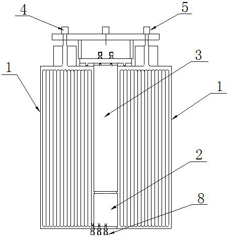
[0046] Such as Figure 1~9 As shown, a non-catalytic reforming reactor includes a heat exchange zone 1, a mixing zone 2, and a reforming reaction zone 3, and is characterized in that: the heat exchanging zone 1 is in the outer layer, and the inner layer is a mixing zone 2 and a reforming reaction zone 3; the mixing zone 2 is located below the reforming reaction zone 3;

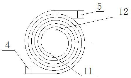
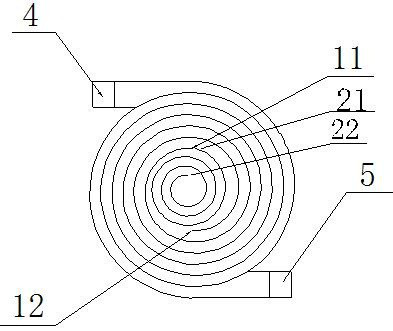
[0047] Heat exchange zone 1 is constructed layer by layer into an end-to-end Swiss roll structure through direct metal laser sintering technology; heat exchange zone 1 realizes heat exchange through the opposite flow of air and product; mixing zone 2 is a detachable spiral tube road 7 structure;

[0048] The reforming reaction zone 3 has a cylindrical structure and is located above the mixing zone 2;

[0049] The air outlet 11 of the heat exchange zone 1 is connected with the air inlet 6 of the mixing zone; the outlet 10 of the mixing zone is connected with the inlet of the reforming reaction zone 3; the out...


PUM

PropertyMeasurementUnit
radiusaaaaaaaaaa

Abstract

The invention discloses a non-catalytic reforming reactor and its technology. The reactor includes a heat exchange zone, a mixing zone and a reforming reaction zone. The heat exchange zone is in the outer layer, and the inner layer is the mixing zone and the reforming reaction zone; The mixing zone is located below the reforming reaction zone; the heat exchange zone is built into an end-to-end Swiss roll structure layer by layer through direct metal laser sintering technology; the heat exchange zone realizes heat exchange through the opposite flow of air and products; the mixing zone is Detachable spiral pipeline structure; the reforming reaction zone is a cylindrical structure, located above the mixing zone. The air outlet of the heat exchange area is connected with the air inlet of the mixing area; the outlet of the mixing area is connected with the inlet of the reforming reaction area; the outlet of the reforming reaction area is connected with the product inlet of the heat exchange area. The invention avoids the use of catalysts; the reactant at the inlet of the heat exchange zone is air, which realizes low-energy and high-efficiency output; the invention responds to the call of green chemistry while improving the reforming yield.

Description

technical field [0001] The invention relates to a non-catalytic reforming reactor and its technology, in particular to the reforming of methane-rich gas produced by hydrocarbon gas liquid fuel, common biomass pyrolysis gas, coking plant, chemical fertilizer plant, oil refining and coal mining, etc. whole device. Background technique [0002] Partial oxidation is an easy way to convert high energy density hydrocarbon fuels (propane, natural gas, gasoline, JP-8, etc.) into syngas, which can easily be used by solid oxide fuel cells (SOFC) to generate electricity, or Further purification is used for high purity hydrogen generation. Since the partial oxidation reformate retains most of the chemical energy, there are some problems in how to utilize this chemical energy. [0003] Catalytic methods have several disadvantages for reforming hydrocarbon fuels. Catalysts also face challenges when fuels contain high concentrations of sulfur species. Sulfur can poison many catalysts, ...

Claims


Application Information

Patent Timeline
Patent Type & Authority Patents(China)
IPC IPC(8): B01J19/24B01J4/00B01J19/00C01B3/36
CPCB01J4/002B01J4/008B01J19/0006B01J19/0013B01J19/0053B01J19/006B01J19/243B01J2204/002B01J2204/007C01B3/36C01B2203/0211
Inventor 张国杰阎煌煜郭晓菲秦晓伟李晟徐英
Owner TAIYUAN UNIV OF TECH
Why Eureka
Try Eureka