Supercharge Your Innovation With Domain-Expert AI Agents!

Modular LED plant illuminating lamp

A technology for lighting lamps and LED light sources, applied in lighting devices, lighting and heating equipment, botanical equipment and methods, etc., can solve the problems of inability to flexibly adjust the light source, the waterproofness of lamps is deteriorated, and the inability to adjust flexibly, and to expand applications Field, increase the variety of changes, the effect of flexible adjustment of light angle and light field

Inactive Publication Date: 2019-04-12
XI AN JIAOTONG UNIV
View PDF4 Cites 1 Cited by
  • Summary
  • Abstract
  • Description
  • Claims
  • Application Information

AI Technical Summary

Problems solved by technology

On the other hand, the growth of each plant has significant differences in light wavelength and light intensity requirements. At present, most of the common LED plant lighting fixtures on the market have fixed dimensions and fixed light spectrum, and cannot flexibly adjust and replace the light source, resulting in a Lamps can only meet the growth needs of one type of plant, and cannot be flexibly adjusted according to different types or even different growth cycles; thirdly, limited by the problem of heat dissipation design, high-power and ultra-high-power LED plant lights on the market generally use wind The cooling and heat dissipation method will cause the waterproof performance of the lamp to deteriorate, and the use of water cooling and heat dissipation will increase the manufacturing cost, which limits its application and promotion

Method used


Image

  • Modular LED plant illuminating lamp
  • Modular LED plant illuminating lamp
  • Modular LED plant illuminating lamp

Examples


Embodiment 1

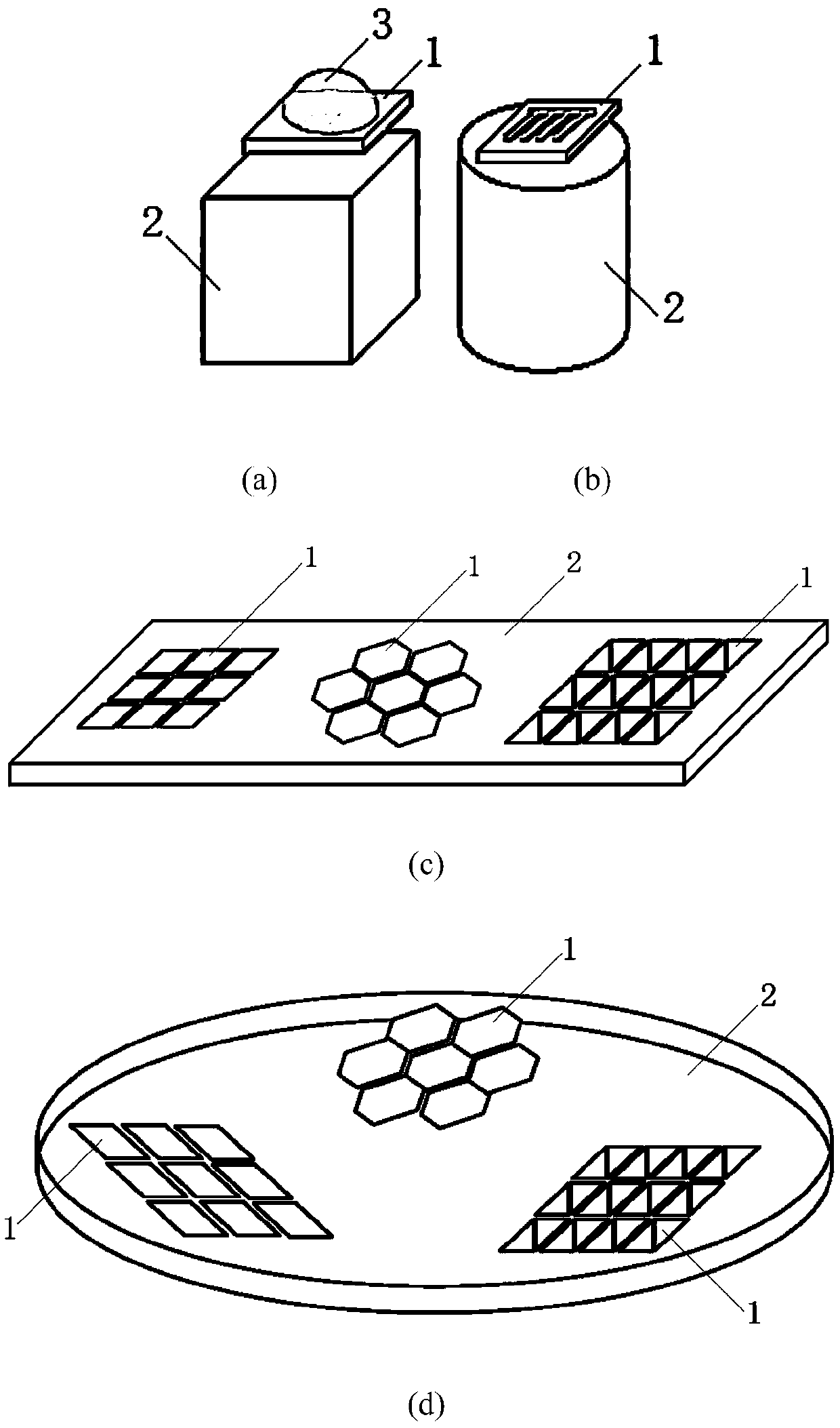
[0032] Embodiment 1: as image 3 As shown, a modular LED plant lighting provided by the present invention, its preparation method specifically includes the following steps:

[0033] (1) First, open holes on the primary heat sink, coat the surface with thermally conductive glue, fix red, blue, green and near-ultraviolet wavelength LED chips from 0.5W to 10W on it, and then use wires to lead from the LED chip The positive and negative leads are connected to the feet to complete the preparation of the LED light source module 1 with the primary heat sink; the heat sink is made of one or more of aluminum, aluminum alloy or copper, copper alloy, aluminum nitride, and heat-conducting ceramics. The glue is one or more combinations of silver glue and insulating glue, and the coating method of thermal conductive glue is one of spraying or dispensing;

[0034](2) Install the LED light source module 1 on the sealed lamp housing 2 with the corresponding installation position. The LED ligh...

Embodiment 2

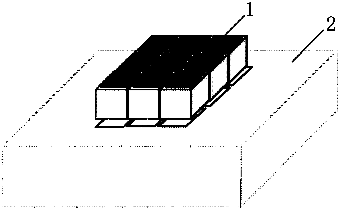
[0037] Embodiment 2: as Figure 4 As shown, a modular LED plant lighting provided by the present invention, its preparation method specifically includes the following steps:

[0038] (1) Firstly, holes are made on the primary heat sink, and a heat conduction layer is prepared on the surface using thin film preparation technology, and red, blue, green and deep ultraviolet wavelength LED chips of 0.5W to 10W are fixed on it, and then Connect the positive and negative leads from the LED chip pins with wires to complete the preparation of the LED light source module 1 with the primary heat sink; the heat sink is made of one of aluminum, aluminum alloy or copper, copper alloy, aluminum nitride, and heat-conducting ceramic One or more, the thermal conductive material is one or more combinations of graphene and high thermal conductivity carbon-based films, and the film preparation technology is one or a combination of chemical or physical vapor deposition;

[0039] (2) The primary o...

Embodiment 3

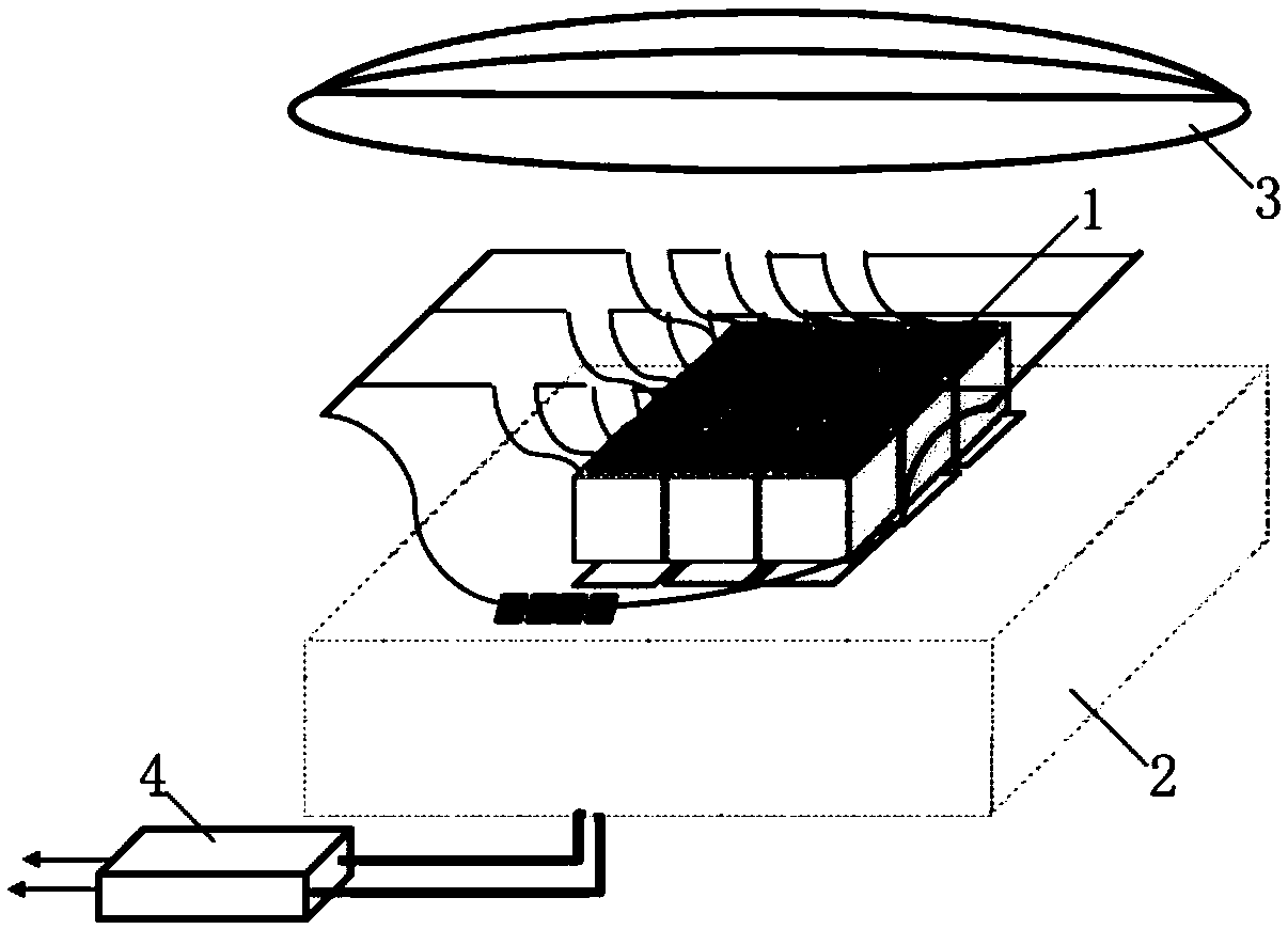
[0043] Embodiment 3: as Figure 5 As shown, a modular LED plant lighting provided by the present invention, its preparation method specifically includes the following steps:

[0044] (1) Firstly, holes are made on the primary heat sink, and a heat conduction layer is prepared on the surface using thin film preparation technology, and red, blue, green and deep ultraviolet wavelength LED chips of 0.5W to 10W are fixed on it, and then Use wires to connect the positive and negative leads from the LED chip pins to complete the preparation of the light source module with the primary heat sink; the heat sink is made of one of aluminum, aluminum alloy or copper, copper alloy, aluminum nitride, heat-conducting ceramics or Various, the thermal conductive material is one or more combinations of graphene and high thermal conductivity carbon-based film, and the film preparation technology is one or a combination of chemical or physical vapor deposition;

[0045] (2) The primary optical le...


PUM


Abstract

The invention discloses a modular LED plant illuminating lamp. The modular LED plant illuminating lamp comprises LED light source modules with primary radiators, a sealing lamp shell with a secondaryradiator, optical modules and a driving power supply, wherein the LED light source modules can be connected with connecting ports preset in the sealing lamp shell serially or in parallel through water-proof conductive wires; mounting positions in array distribution and corresponding to the LED light source modules in number are reserved in the sealing lamp shell; the LED light source modules withthe primary radiators can be directly plugged into or unplugged from the mounting positions; connecting circuit ports capable of achieving direct plugging and unplugging are preset around the mountingpositions of the LED light source modules on the sealing lamp shell; the optical modules are split or integrated optical windows which have different emergent light far-field distribution morphologies and can be processed from a variety of materials, and are mounted above the corresponding LED light source modules; the driving power supply adopts a pulsed or DC working mode to achieve individualcontrol of the LED light source modules or unified control of all the LED light source modules. The modular LED plant illuminating lamp has the advantage of full use of a modular design concept.

Description

technical field [0001] The invention belongs to the field of plant lighting, in particular to a modular LED plant lighting lamp. Background technique [0002] During the growth process, plants not only need to use light to carry out photosynthesis to obtain the energy and nutrients needed for growth, but also need to use light to improve development, flowering, deformation and other processes. In nature, sunlight is the easiest light source to obtain, but sunlight is greatly affected by environmental factors, and its stability cannot be guaranteed. Therefore, artificial lighting is used to supplement light to improve the yield and quality of crops. Plant lighting technology is the current A hot area of ​​development. [0003] Traditional light sources such as high-pressure sodium lamps and fluorescent lamps commonly used in early plant lighting to achieve plant lighting, on the one hand, have poor wavelength pertinence and relatively short service life. Compared with LED li...

Claims


Application Information

Patent Timeline
IPC IPC(8): F21K9/20F21V5/04F21V9/40F21V19/00F21V23/00F21V29/507F21V29/56A01G7/04F21V29/60F21V29/70F21V29/83F21V29/85F21V31/00F21Y115/10
CPCA01G7/04F21K9/20F21V5/04F21V9/40F21V19/00F21V23/003F21V29/507F21V29/56F21V29/60F21V29/70F21V29/83F21V29/85F21V31/005F21Y2115/10Y02P60/14
Inventor 张敏妍云峰郭茂峰赵丁苏喜林李琨
Owner XI AN JIAOTONG UNIV
Features
  • R&D
  • Intellectual Property
  • Life Sciences
  • Materials
  • Tech Scout
  • Unparalleled Data Quality
  • Higher Quality Content
  • 60% Fewer Hallucinations
Learn More