A sinter draft type vertical cooling furnace and a sinter cooling method

A technology for cooling furnace and sinter, which is applied in the field of sinter cooler and sinter cooling, sinter ventilation vertical cooling furnace and sinter cooling, which can solve the problems of high fan power consumption, low sensible heat recovery rate and boiler thermal efficiency low level problem

Active Publication Date: 2020-08-28
ZHONGYE-CHANGTIAN INT ENG CO LTD
View PDF8 Cites 0 Cited by
  • Summary
  • Abstract
  • Description
  • Claims
  • Application Information

AI Technical Summary

Problems solved by technology

No matter which cooling method is used, the cooling machine has problems such as large air leakage rate, high fan power consumption, low sensible heat recovery rate, and low boiler thermal efficiency.
In other words, in the current environment where the market has increasingly stringent requirements for energy saving and green manufacturing in sinter production, the original equipment structure has been difficult to achieve efficient recovery and utilization of sinter sensible heat

Method used


Image

  • A sinter draft type vertical cooling furnace and a sinter cooling method
  • A sinter draft type vertical cooling furnace and a sinter cooling method
  • A sinter draft type vertical cooling furnace and a sinter cooling method

Examples


Embodiment 1

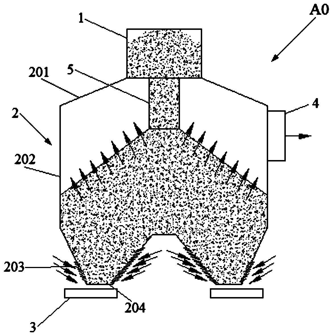
[0077] Such as figure 1 As shown, a sinter draft type vertical cooling furnace, the vertical cooling furnace A0 includes a silo 1, a tower body 2 and a discharge device 3. The tower body 2 includes a tower top 201 , a tower wall 202 and an air inlet section 203 . The tower top 201 is arranged at the top of the tower wall 202 , and the air inlet section 203 is arranged at the lower part of the tower wall 202 . The feed bin 1 is arranged above the tower top 201 and communicates with the inside of the tower body 2 . A discharge port 204 is provided at the bottom of the air inlet section 203 . The discharge device 3 is arranged below the discharge opening 204 . The upper part of the tower wall 202 is provided with an exhaust type hot air outlet 4 . The discharge device 3 is an electric vibration feeder.

Embodiment 2

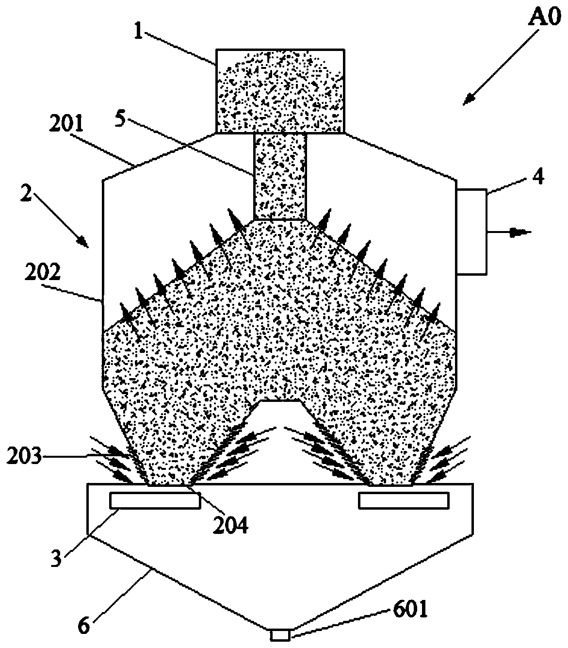
[0079] Such as figure 2 and 5 As shown, a sinter draft type vertical cooling furnace, the vertical cooling furnace A0 includes a silo 1, a tower body 2 and a discharge device 3. The tower body 2 includes a tower top 201 , a tower wall 202 and an air inlet section 203 . The tower top 201 is arranged at the top of the tower wall 202 , and the air inlet section 203 is arranged at the lower part of the tower wall 202 . The feed bin 1 is arranged above the tower top 201 and communicates with the inside of the tower body 2 . A discharge port 204 is provided at the bottom of the air inlet section 203 . The discharge device 3 is arranged below the discharge opening 204 . The upper part of the tower wall 202 is provided with an exhaust type hot air outlet 4, but the vertical cooling furnace A0 also includes a material seal distribution pipe 5. The top of the material seal material distribution pipe 5 is connected with the feed bin 1, and the material seal material distribution pi...

Embodiment 3

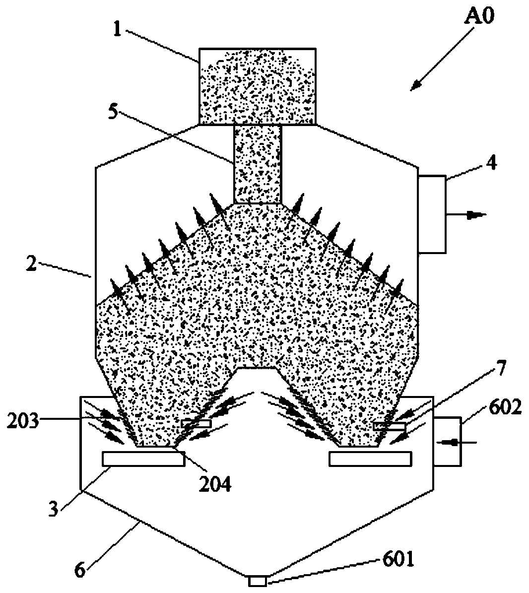
[0081] Such as image 3 As shown, embodiment 2 is repeated, only the top of the discharge chute 6 is connected to the upper part of the side wall of the air inlet section 203, and the air inlet section 203 and the discharge device 3 are located at the outer side wall of the discharge chute 6 and the air inlet section 203. inside the space. The bottom of the discharge chute 6 is provided with a discharge port 601 , and the side wall of the discharge chute 6 is provided with a cold air inlet 602 .


PUM

PropertyMeasurementUnit
diameteraaaaaaaaaa

Abstract

The invention discloses a sinter air drafting type vertical cooling furnace. The vertical cooling furnace (A0) comprises a stock bin (1), a tower body (2) and discharging equipment (3). The tower body(2) comprises a tower top (201), a tower wall (202) and an air inlet segment (203). The tower top (201) is arranged on the top of the tower wall (202), and the air inlet segment (203) is arranged onthe lower part of the tower wall (202). The stock bin (1) is arranged on the upper part of the tower top (201) and communicates with the interior of the tower body (2). The bottom of the air inlet segment (203) is provided with a discharge port (204). The discharging equipment (3) is arranged below the discharge port (204). The tower top (201) or the upper part of the tower wall (202) is providedwith an air drafting hot air outlet (4). The vertical cooling furnace has the advantages that the sinter cooling speed is low, the cooling air capacity consumed per ton is small, the exhaust gas quantity is relatively small, the exhaust gas temperature is high, the boiler thermal efficiency is high, cooling waste gas can be completely utilized by a boiler, and the sensible heat recovery rate of sinter generally can reach about 70 %.

Description

technical field [0001] The invention relates to a sinter cooler and a sinter cooling method, in particular to a sinter draft type vertical cooling furnace and a sinter cooling method, belonging to the fields of ironmaking and environmental protection. Background technique [0002] In recent years, with the increasingly tense relationship between energy consumption and environmental protection in my country, energy conservation and environmental protection have been valued by the whole society, making it a key measure to establish a resource-saving and environment-friendly society. Energy conservation and environmental protection work involves all aspects. Energy conservation and environmental protection in the industrial field is the focus and difficulty of energy conservation and environmental protection work, especially for the steel industry with high energy consumption and heavy environmental pollution. The energy consumption of the sintering process accounts for about 1...

Claims


Application Information

Patent Timeline
Patent Type & Authority Patents(China)
IPC IPC(8): F27D15/02F27D17/00
CPCF27D15/0286F27D17/004F27M2003/04Y02P10/25
Inventor 张震贺新华
Owner ZHONGYE-CHANGTIAN INT ENG CO LTD
Why Eureka
Try Eureka