Flue gas treatment and resource recovery system

A technology for resource recovery and flue gas recovery, applied in the system field of flue gas treatment and resource recovery, can solve the problems of microbial cell toxicity, limit the efficiency of flue gas treatment and energy recovery, and fail to grow, so as to avoid toxic effects, Ensure efficient growth and avoid high energy consumption

Inactive Publication Date: 2019-04-23
CHONGQING UNIV OF TECH
View PDF5 Cites 1 Cited by
  • Summary
  • Abstract
  • Description
  • Claims
  • Application Information

AI Technical Summary

Problems solved by technology

However, when the industrial flue gas is directly passed into the microbial energy conversion system for flue gas treatment, the high concentration of complex gas components in the flue gas (mainly acid gas components, such as CO 2 , SO 2 , NO x etc.) will cause strong poisonous effect on microbial cells and make them unable to grow, which greatly limits the efficiency of flue gas treatment and energy recovery efficiency

Method used


Image

  • Flue gas treatment and resource recovery system
  • Flue gas treatment and resource recovery system

Examples


Embodiment 1

[0024] Example 1 The flue gas treatment and resource recovery system of the present invention treats industrial flue gas

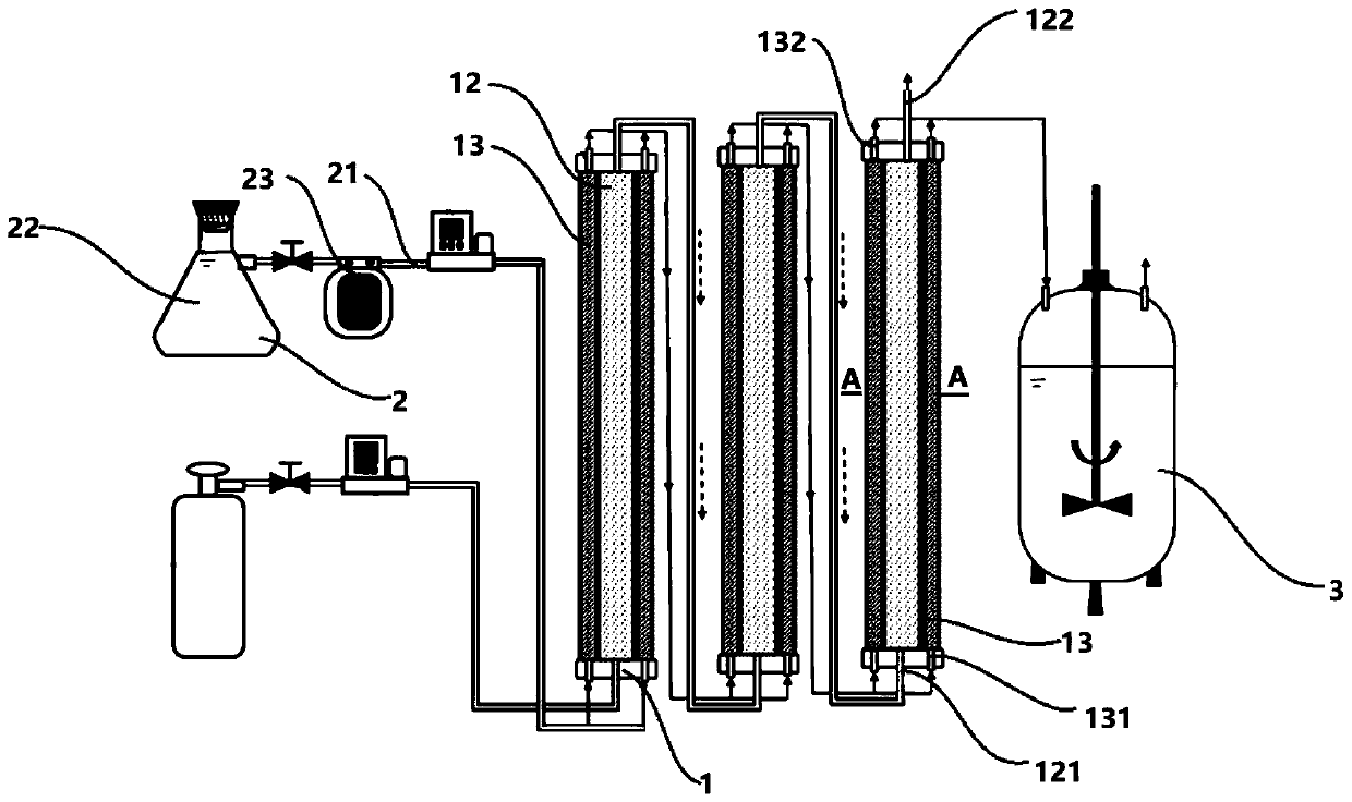
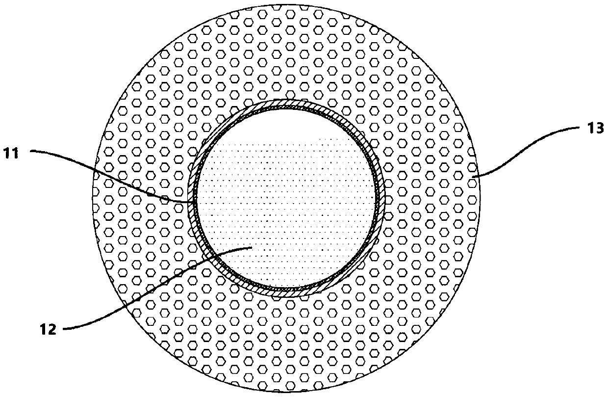
[0025] The first step: construction of a new system, which includes: microbial supply unit 2, 3 flue gas recovery units 1 and production unit 3 in series, see figure 2, the flue gas recovery unit 1 is a hollow tube with both ends sealed, the hollow tube is made of transparent material, an inner tube with the same length is arranged inside the hollow tube, the surface of the inner tube is hollowed out, and an anion exchange membrane 11 is adhered, The inner pipe is an alkaline absorption chamber, and what the inner pipe and the outer pipe form a chamber is a microbial absorption chamber 12; the bottom of the alkaline absorption chamber 12 is provided with a flue gas inlet 121, and the alkaline absorption chamber 12 The top of the microbial absorption chamber is provided with a flue gas outlet 122; the bottom 13 of the microorganism absorption chamber is pr...

Embodiment 2

[0029] Example 2 The flue gas treatment and resource recovery system of the present invention treats automobile exhaust

[0030] The first step: construction of a new system, which includes: microbial supply unit 2, 3 flue gas recovery units 1 and production unit 3 in series, see figure 2 , the flue gas recovery unit 1 is a hollow tube with both ends sealed, the hollow tube is made of transparent material, an inner tube with the same length is arranged inside the hollow tube, the surface of the inner tube is hollowed out, and an anion exchange membrane 11 is adhered, The inner pipe is an alkaline absorption chamber, and what the inner pipe and the outer pipe form a chamber is a microbial absorption chamber 12; the bottom of the alkaline absorption chamber 12 is provided with a flue gas inlet 121, and the alkaline absorption chamber 12 The top of the microbial absorption chamber is provided with a flue gas outlet 122; the bottom 13 of the microorganism absorption chamber is pr...


PUM


Abstract

The invention relates to the field of resource recovery, particularly to a flue gas treatment and resource recovery system. The flue gas treatment and resource recovery system is composed of one or more flue gas recovery units which are connected in series; every flue gas recovery unit comprises an alkaline absorbing chamber and a microorganism absorbing chamber which are separated by an anion-exchange membrane, alkaline absorbing agent is filled inside the alkaline absorbing chamber, the lower portion or the bottom of the alkaline absorbing chamber is provided with a flue gas inlet, the top or the upper portion of the alkaline absorbing chamber is provided with a flue gas outlet, the microorganism absorbing chamber is made of transparent materials and filled with microorganism culture solution, microorganisms are inoculated into the microorganism culture solution, and the microorganism absorbing chamber is provided with a microorganism culture solution inlet. The flue gas treatment and resource recovery system can absorb and utilize carbon dioxide, sulfur dioxide and nitrogen oxide in flue gas for immobilization to produce biological oil and the like and meanwhile maintain efficient growth of contained microorganisms.

Description

technical field [0001] The invention relates to the field of resource recovery, in particular to a system for flue gas treatment and resource recovery. Background technique [0002] With the acceleration of urbanization and the expansion of urban population, environmental pollution has become a major problem facing the development of human society, especially the pollution of the atmospheric environment has seriously affected human life. At present, my country's air pollution mainly comes from industrial emissions. The latest data show that from 2000 to 2011, the average annual growth rate of China's industrial waste gas emissions was 19.06%, from 13.8145 billion standard cubic meters in 2000 to 67.4509 billion standard Cubic meters, an increase of 2.39 times in 11 years. Industrial flue gas contains a lot of SO x , NO x , CO 2 Such acidic gas components, after being discharged into the air without treatment, will cause environmental problems such as acid rain, smog, and ...

Claims


Application Information

Patent Timeline
Patent Type & Authority Applications(China)
IPC IPC(8): B01D53/78B01D53/40B01D53/84B01D53/75B01D53/60B01D53/62C12M1/00
CPCB01D53/40B01D53/60B01D53/62B01D53/75B01D53/78B01D53/84B01D2251/95B01D2258/0283C12M21/02C12M23/22Y02P20/59Y02A50/20
Inventor 常海星全学军杨静谭玲杨啟铭张婷钟年丙杨鑫
Owner CHONGQING UNIV OF TECH
Why Eureka
Try Eureka