Hot secondary air and flue gas waste heat utilization system and thermal power generating unit

A flue gas waste heat and secondary air technology, applied in the field of flue gas waste heat utilization, can solve the problems of high equipment cost, high dust content in flue gas, complex system, etc., achieve high utilization rate of flue gas waste heat, save equipment cost, The effect of improving boiler efficiency

Pending Publication Date: 2019-04-23
CHINA POWER ENG CONSULTING GRP CORP EAST CHINA ELECTRIC POWER DESIGN INST
View PDF1 Cites 4 Cited by
  • Summary
  • Abstract
  • Description
  • Claims
  • Application Information

AI Technical Summary

Problems solved by technology

The existing air preheater bypass economizer system can efficiently utilize the boiler flue gas waste heat, but due to the high dust content of the bypass flue gas and certain corrosiveness, the flue gas heat exchanger needs to Considering the problems of anti-wear and anti-corrosion, there are certain risks, and complex soot blowing systems and equipment need to be installed. The equipment costs are high, the system is relatively complicated, and the flue gas heat exchanger is easy to wear, which affects the safe operation of the unit.

Method used


Image

  • Hot secondary air and flue gas waste heat utilization system and thermal power generating unit
  • Hot secondary air and flue gas waste heat utilization system and thermal power generating unit
  • Hot secondary air and flue gas waste heat utilization system and thermal power generating unit

Examples


Embodiment

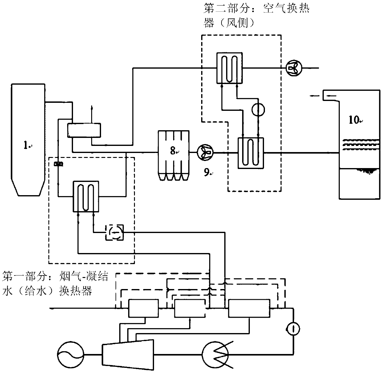
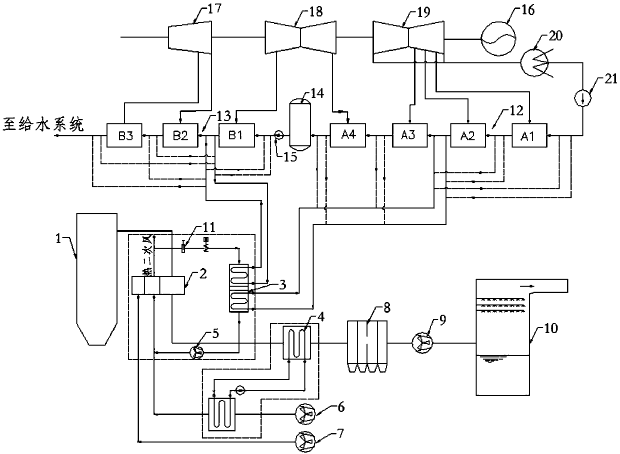
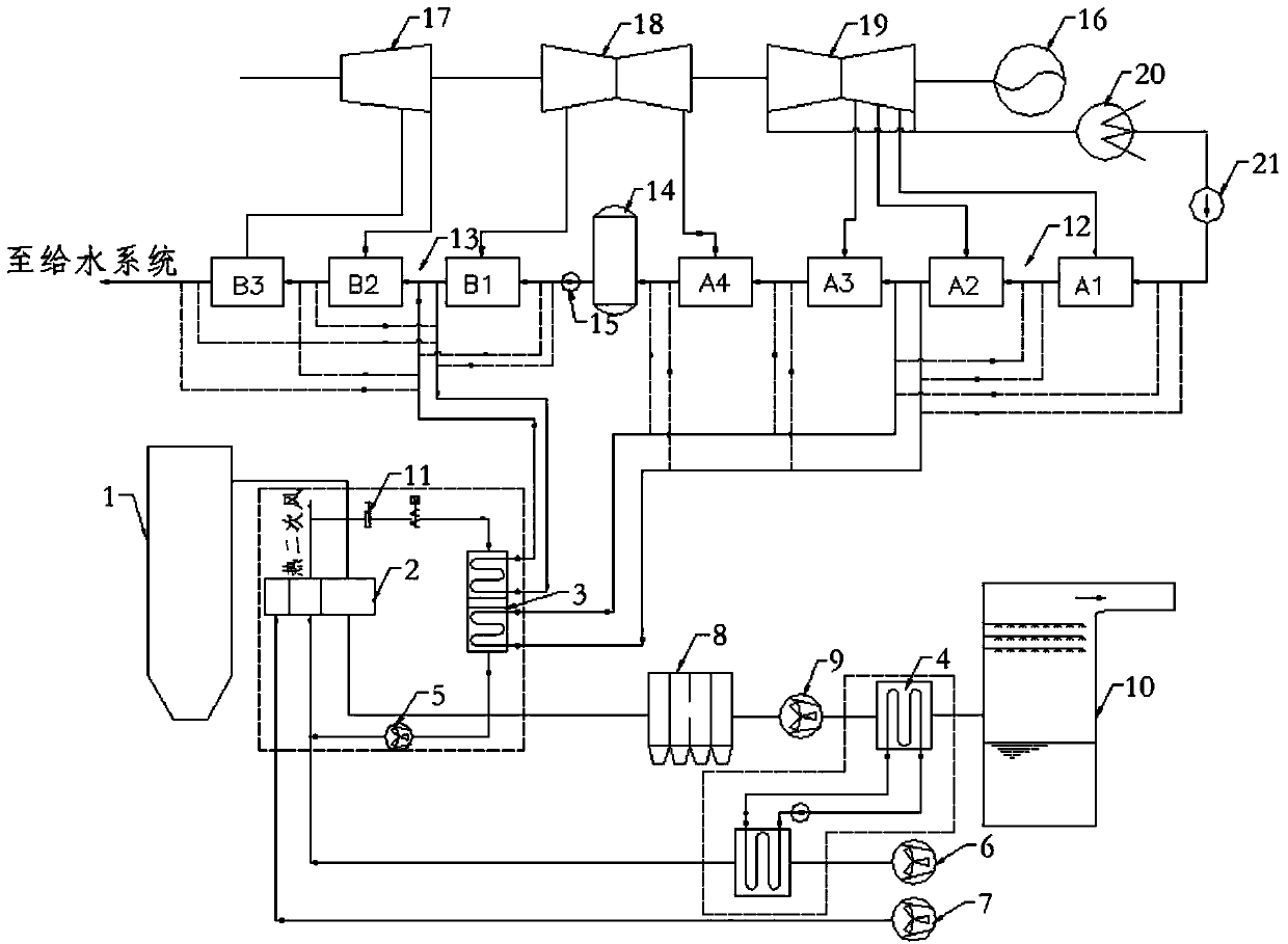
[0096] Such as figure 2 and image 3 As shown, a hot secondary air and flue gas waste heat utilization system includes boiler 1, air preheater 2, hot secondary air-feed water / condensate heat exchanger 3, flue gas-air heat exchanger 4, bypass Road secondary fan 5, air blower 6, primary fan 7, dust collector 8, air induction device 9, absorption tower 10, low pressure heater 12 and high pressure heater 13;

[0097] Among them, the air preheater 2 is provided with a flue gas inlet, a primary cold air inlet, a secondary cold air inlet, a flue gas outlet and a hot secondary air outlet; the flue gas inlet of the air preheater 2 is connected with the flue gas outlet of the furnace of the boiler 1 , the air preheater 2 is connected to the primary fan 7 through the primary cold air inlet, the gas outlet pipeline of the hot secondary air-feed water / condensate water heat exchanger 3 is provided with a bypass secondary fan 5, and the blower 6 is connected to the flue gas-air The heat e...


PUM


Abstract

The invention belongs to the technical field of flue gas waste heat utilization and relates to a hot secondary air and flue gas waste heat utilization system and a thermal power generating unit. The hot secondary air and flue gas waste heat utilization system comprises an air preheater, a dedustor, an absorption tower, a hot secondary air-feedwater / condensate heat exchanger and a flue gas-air heatexchanger; a hot secondary air outlet of the air preheater is connected with a hot secondary air bypass, the hot secondary air bypass is connected with the hot secondary air-feedwater / condensate heatexchanger, and feedwater / condensate is heated by means of hot secondary air; and the flue gas-air heat exchanger is arranged in an inlet of the dedustor, and cold air is heated by means of low-temperature flue gas at the inlet of the dedustor; or the flue gas-air heat exchanger is arranged in an inlet of the absorption tower, and the cold air is heated by means of low-temperature flue gas at theinlet of the absorption tower. The hot secondary air and flue gas waste heat utilization system and the thermal power generating unit are high in flue gas waste heat utilization rate, and have the characteristics of being clean, free of abrasion, free of corrosion and the like, no soot blowing system is needed, the equipment cost is low, and operation is safe and reliable.

Description

technical field [0001] The invention belongs to the technical field of flue gas waste heat utilization, and in particular relates to a hot secondary air and flue gas waste heat utilization system and a thermal power generation unit. Background technique [0002] At present, my country's power generation is still dominated by coal power, and coal power, as the main body of my country's power production, still has a lot of room for development. Coal is the largest source of carbon dioxide emissions in my country, and coal power companies are the largest carbon dioxide emitters. At present, the most effective and realistic way to reduce emissions is to improve power generation efficiency, so efficient and clean coal power technology is the main direction of future development. The emission of pollutants is related to the coal consumption of thermal power plants. It is a promising technology to reduce the emission of pollutants from thermal power plants to the atmosphere while ...

Claims


Application Information

Patent Timeline
Patent Type & Authority Applications(China)
IPC IPC(8): F23J15/06F23J15/02F23L15/04F22B1/18F01K27/00
CPCF01K27/00F22B1/18F23J15/022F23J15/06F23L15/04Y02E20/34
Inventor 顾欣胡忠霞施刚夜申松林邓文祥林磊张未国侯新建
Owner CHINA POWER ENG CONSULTING GRP CORP EAST CHINA ELECTRIC POWER DESIGN INST
Why Eureka
Try Eureka