
A Quantum Well Infrared Circularly Polarized Detector

A detector and quantum well technology, applied in the direction of measuring the polarization of light, instruments, measuring devices, etc., can solve the problem that the detector cannot distinguish different infrared circularly polarized light, and achieve small size, high integration, and process robustness Good results

Active Publication Date: 2020-06-26
SHANGHAI INST OF TECHNICAL PHYSICS - CHINESE ACAD OF SCI
View PDF1 Cites 1 Cited by
  • Summary
  • Abstract
  • Description
  • Claims
  • Application Information

AI Technical Summary

Problems solved by technology

[0006] The purpose of the present invention is to propose a quantum well circularly polarized detector to solve the problem that traditional detectors cannot distinguish different infrared circularly polarized lights

Method used


Image

  • A Quantum Well Infrared Circularly Polarized Detector
  • A Quantum Well Infrared Circularly Polarized Detector
  • A Quantum Well Infrared Circularly Polarized Detector

Examples


Embodiment 1

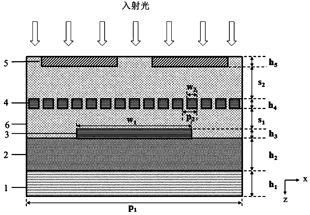
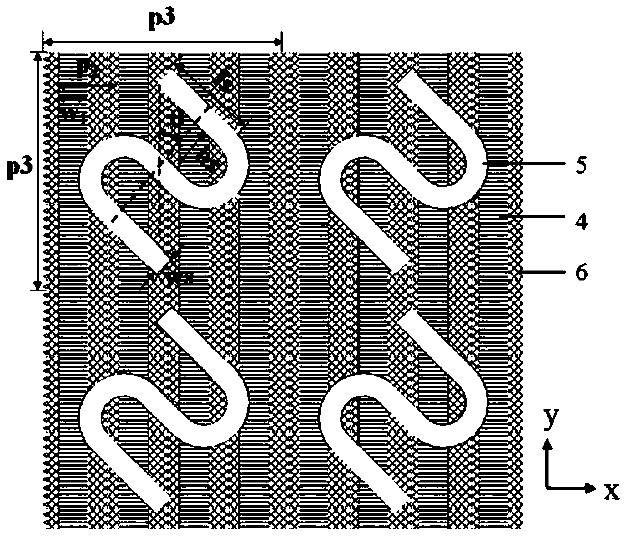
[0037] The detection incident wavelength of the quantum well circular polarization detector in this embodiment is 9.8 μm, gold is used as the metal, and calcium fluoride with a refractive index of 1.43 is used for the dielectric layer 6 transparent to the working wavelength band. The structural size is: metal reflector 1 thickness h 1 = 0.5 μm, quantum well infrared photoelectric conversion active layer 2 thickness h 2 =0.9μm, the refractive index is 3.3, and the large period grating has 3 periods p 1 =6.2μm, bar width w 1 =4.5μm, small-period sub-wavelength metal grating with 4 periods p 2 =0.8μm, bar width w 2 = 0.4 μm, the two-dimensional metal metasurface 5 adopts a metal S-shaped array, and the period p 2 = 3.1 μm, line width ws = 0.3 μm, ls = hs = 0.6 μm, θ = 45°. Large period metal grating 3 bar height h 3 , small-period sub-wavelength metal grating 4 bar height h 4 and a metal S-shaped array of 5 height h 5 Both are 0.3μm, the distance between the large-period ...

Embodiment 2

[0040] The detection incident wavelength of the quantum well circular polarization detector in this embodiment is 9.8 μm, and the grid width w of the small-period sub-wavelength metal grating 4 is changed in this embodiment on the basis of embodiment 1 2 , so that the bar width w 2 with period p 2 The ratio is reduced to 0.2, the metal is made of aluminum, and its structural size is: metal reflector 1 thickness h 1 = 0.5 μm, quantum well infrared photoelectric conversion active layer 2 thickness h 2 =0.9μm, the refractive index is 3.3, and the large-period metal grating has 3 periods p 1 =6.2μm, bar width w1 =4.5μm, small-period sub-wavelength metal grating with 4 periods p 2 =0.8μm, bar width w 2 =0.2μm, metal S-shaped array with 5 periods p 3 = 3.2 μm, line width ws = 0.3 μm, ls = hs = 0.6 μm, θ = 45°. Large period metal grating 3 bar height h 3 , small-period sub-wavelength metal grating 4 bar height h 4 and a metal S-shaped array of 5 height h 5 Both are 0.3μm, th...

Embodiment 3

[0043] The detection incident wavelength of the quantum well circular polarization detector in this embodiment is 9.8 μm, and this embodiment changes the grid width w of the small periodic grating on the basis of embodiment 1 2 , so that the bar width w 2 with period p 2 The ratio is increased to 0.8, silver is used as the metal, and barium fluoride with a refractive index of 1.47 is used for the medium layer 6 transparent to the working band, and its structural size is: the thickness h of the metal reflector 1 1 = 0.5 μm, quantum well infrared photoelectric conversion active layer 2 thickness h 2 =0.9μm, the refractive index is 3.3, and the large-period metal grating has 3 periods p 1 =6.2μm, bar width w 1 =4.5μm, small-period sub-wavelength metal grating with 4 periods p 2 =0.8μm, bar width w 2 =0.64μm, metal S-shaped array 5 periods p 3 = 3.2 μm, line width ws = 0.3 μm, ls = hs = 0.6 μm, θ = 45°. Large period metal grating 3 bar height h 3 , small-period sub-wavelen...


PUM


Abstract

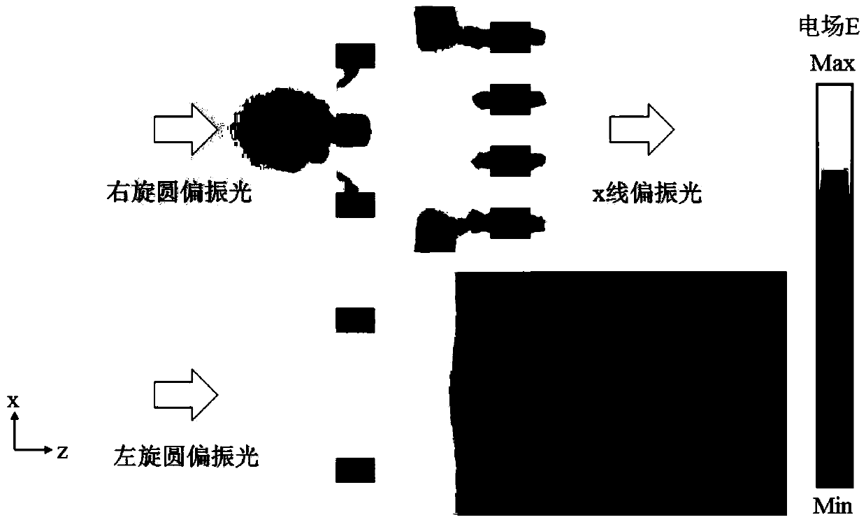
The invention discloses a quantum well infrared circular polarization detector. The quantum well infrared circular polarization detector structurally comprises a metal reflector, a quantum well infrared photoelectric conversion activation layer, a large-period metal grating, a small-period sub-wavelength metal grating and a two-dimensional metal metasurface, wherein the large-period metal grating,the small-period sub-wavelength metal grating and the two-dimensional metal metasurface are embedded in a dielectric layer which is transparent for working wavebands. By utilizing the two-dimensionalmetal metasurface and the small-period sub-wavelength metal grating, a selection and conversion cavity is formed, so that specific types of circularly polarized light can be selected to be transmitted and then converted into corresponding linearly polarized light; and the large-period metal grating and the metal reflector form a plasmon micro cavity, so that the direction of photon electric vectors passing through the selection and conversion cavity is converted from an x direction to a z direction to ensure that the photon electric vectors can be absorbed by energy quantum well sub-band transition to realize photoelectric conversion. Meanwhile, the micro cavity is capable of effectively the electric field intensity of a quantum well infrared photoelectric conversion activation area to further enhance the photon absorption, thereby realizing the selection and detection, for circularly polarized light, of the detector.

Description

technical field [0001] The invention relates to an infrared circular polarization detector, in particular to a quantum well infrared circular polarization detector. Background technique [0002] When natural light interacts with matter, it will introduce polarization states related to material properties (such as roughness, material, water content, etc.) in refracted light, reflected light, scattered light, and thermal radiation. Therefore, polarization imaging can not only effectively identify low-contrast targets that traditional intensity imaging cannot or is difficult to distinguish, but also highlight the outline features of target objects. Navigation, camouflage recognition, sea surface and underwater target detection and recognition have advantages that traditional technologies do not have, and are a new means of information analysis. [0003] The polarization state of light can be divided into linear polarization state and circular polarization state. At present, t...

Claims


Application Information

Patent Timeline
Patent Type & Authority Patents(China)
IPC IPC(8): H01L31/101H01L31/0232G01J4/04G01J4/00
Inventor 王少伟李辰璐冀若楠李宁李志锋陆卫
Owner SHANGHAI INST OF TECHNICAL PHYSICS - CHINESE ACAD OF SCI
Learn More